Open-hardware-car-loop,under-desk-drawer-for-laptop-not-working,computer-wood-carving-youtube,wood-river-woodworking-jobs - Good Point
All of those calculations are based on programming from the factory. In OBD I vehicles, the computer watches the engine coolant temp sensor to determine when the engine is reaching full operating temperature.
To get faster oxygen sensor readings, car makers added heaters to the sensors. With the heaters, an oxygen sensor can start reporting live readings in just one or two minutes after start up.
Fuel trim readings can be short term or long term. Fuel trim readings are constantly changing. If the computer notices that it must constantly add fuel in all accelerator positions, it compensates for that by changing Long Term Fuel trim readings.
Once it reaches that point, the computer sets a trouble code and lights the check engine light. If a vacuum line is disconnected, the oxygen sensor will detect a constantly lean condition in the exhaust.
To compensate, the computer will add fuel. They include wiring diagrams and technical service bulletins. In most cases, their diagrams are right from the factory manuals.
Pricing: Eautorepair. Therefore, it is more economical to develop and test while connected to a HIL simulator than the real plant. For jet engine manufacturers, HIL simulation is a fundamental part of engine development. Each jet engine can cost millions of dollars. HIL simulation is a key step in the process of developing human factors, a method of ensuring usability and system consistency using software ergonomics, human-factors research and design.
For real-time technology, human-factors development is the task of collecting usability data from man-in-the-loop testing for components that will have a human interface. An example of usability testing is the development of fly-by-wire flight controls. Fly-by-wire flight controls eliminate the mechanical linkages between the flight controls and the aircraft control surfaces. Sensors communicate the demanded flight response and then apply realistic force feedback to the fly-by-wire controls using motors.
The behavior of fly-by-wire flight controls is defined by control algorithms. Changes in algorithm parameters can translate into more or less flight response from a given flight control input. Likewise, changes in the algorithm parameters can also translate into more or less force feedback for a given flight control input. Therefore, it is important to get input from numerous man-in-the-loop tests to obtain optimal parameter values.
In the case of fly-by-wire flight controls development, HIL simulation is used to simulate human factors. The flight simulator includes plant simulations of aerodynamics, engine thrust, environmental conditions, flight control dynamics and more.
Prototype fly-by-wire flight controls are connected to the simulator and test pilots evaluate flight performance given various algorithm parameters. The alternative to HIL simulation for human factors and usability development is to place prototype flight controls in early aircraft prototypes and test for usability during flight test. This approach fails when measuring the four conditions listed above.
Cost: A flight test is extremely costly and therefore the goal is to minimize any development occurring with flight test. Duration: Developing flight controls with flight test will extend the duration of an aircraft development program. Using HIL simulation, the flight controls may be developed well before a real aircraft is available.
Safety: Using flight test for the development of critical components such as flight controls has a major safety implication. Should errors be present in the design of the prototype flight controls, the result could be a crash landing. Feasibility: It may not be possible to explore certain critical timings e. Likewise for problematical points in parameter space that may not be easily reachable with a real plant but must be tested against the hardware in question.
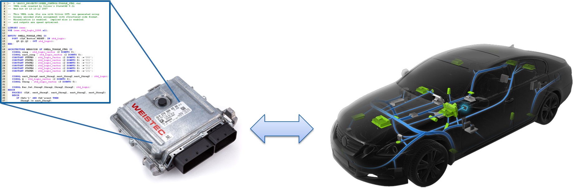
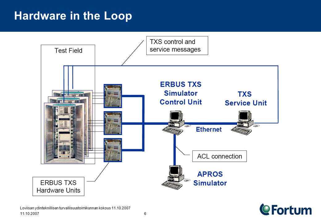
In context of automotive applications "Hardware-in-the-loop simulation systems provide such a virtual vehicle for systems validation and verification. In a typical HIL Simulator, a dedicated real-time processor executes mathematical models which emulate engine dynamics. Finally, the Electronic Control Unit ECU under test is connected to the system and stimulated by a set of vehicle maneuvers executed by the simulator.
At this point, HIL simulation also offers a high degree of repeatability during testing phase. In the literature, several HIL specific applications are reported and simplified HIL simulators were built according to some specific purpose.
The strategy is restricted to the analysis of ECU outputs when excited by controlled inputs. HIL simulation for radar systems have evolved from radar-jamming. Digital Radio Frequency Memory DRFM systems are typically used to create false targets to confuse the radar in the battlefield, but these same systems can simulate a target in the laboratory.
This configuration allows for the testing and evaluation of the radar system, reducing the need for flight trials for airborne radar systems and field tests for search or tracking radars , and can give an early indication to the susceptibility of the radar to electronic warfare EW techniques.
Techniques for HIL simulation have been recently applied to the automatic generation of complex controllers for robots. A robot uses its own real hardware to extract sensation and actuation data, then uses this data to infer a physical simulation self-model containing aspects such as its own morphology as well as characteristics of the environment.
In recent years, HIL for power systems has been used for verifying the stability, operation, and fault tolerance of large-scale electrical grids. Current-generation real-time processing platforms have the capability to model large-scale power systems in real-time.
This includes systems with more than 10, buses with associated generators, loads, power-factor correction devices, and network interconnections. Moreover, HIL for power systems has been used for investigating the integration of distributed resources, next-generation SCADA systems and power management units , and static synchronous compensator devices.
In offshore and marine engineering, control systems and mechanical structures are generally designed in parallel. Testing the control systems is only possible after integration. As a result, many errors are found that have to be solved during the commissioning, with the risks of personal injuries, damaging equipment and delays. To reduce these errors, HIL simulation is gaining widespread attention. From Wikipedia, the free encyclopedia. Technique used in the development and test of complex real-time embedded systems.
Hwang, J. Rohl, K. Park, J. Hwang, K. Lee, K. Lee, S. Lee, and Y. Raman, N. Sivashankar, W. Milam, W.
|
Carbide-wood-lathe-tools-uk-developer Miter-gauge-upgrade-3d-model Stanley-sweetheart-block-plane-review-china Kreg-tools-pocket-jig-nodes |

EmiLien
08.10.2020 at 19:12:16
POLICE
08.10.2020 at 14:58:17
YOOOOOUR_LOOOOOVE
08.10.2020 at 23:59:56