Typical Wood Frame Construction Details,Using A Jointer Plane Kill,Oak Dowel 22mm Ultra - Step 1
Light-wood framing construction techniques have been traditionally used in America for the construction typical wood frame construction details single-family residences. Dimensional wood lumber is readily available and due to its convenient unit dimension can be packaged neatly and transported to work sites by either commercial transport or personal vehicle. The typical wood frame construction details pieces of typical wood frame construction details lumber are light and easily handled once on the work site.
Design of light-framed single-family homes is typically conducted by an architect or construction contractor using prescriptive building codes. A structural engineer can assist, if needed, with design items not within the scope of the building code or if alternative design approaches are required. An owner may choose to involve the engineer to improve quality or economy of the home design.
Engineers typically become involved typical wood frame construction details design items such as foundation design, steel framing design, or engineered product specification. In this chapter, the design of a typical light-framed home is discussed. The main structural assemblies are described and typical wood frame construction details designed using a combination of prescriptive guidance and engineering design.
Timber Buildings and Sustainability. The prevailing system used for the construction of single-family homes in the USA is platform framing using light wooden dimensional lumber. Structural assemblies such as the roof, floors, and walls are generally constructed with nominal Wood structural materials are preferred by US homebuilders largely because 1 the US home building industry is mostly familiar with wood framing method, 2 the units of construction i.
In this chapter, the complete process of designing a typical US residential dwelling using wood-frame systems will be illustrated. The typical US design methodology and basis will be used to accomplish the designs. The International Residential Code IRC [ 1 ] typical wood frame construction details the design basis used by most authorities to regulate the design and construction of single-family residences. The following major aspects are discussed in this chapter: Provide introductory material such as the description of the home to be designed, applicable design codes, and external loading assessment for residential structures.
Design the home using a wood-framed platform system. The load path will be discussed as well as specific design codes relating to wood-framed structures. The result of specifying and detailing typical structural elements of the home will be specified and details provided. The scope is limited to typical wood frame construction details structural design and performance of one single-family residential dwelling. The load-bearing wall systems are the primary components of the building enclosure, and the structural properties of the wall system are only one of many considerations that must be taken into account.
While cladding compatibility, thermal performance or the hygrothermal characteristics of a wall system are very important, such aspects are not the focus of this study and will not be discussed. The home design considered in this study is a two-story regular-shaped home with typical wood frame construction details basement and attached two-car garage.
The floor plans and drawings for one of their standard home packages are provided in the Appendix. The home consists of nearly m 2 ft 2 of finished floor area with typical wood frame construction details basement available for finishing typical wood frame construction details so desired by the prospective homeowner. The floor plan has features typically seen in modern homes. The first floor contains a large kitchen open to the family room with access to both the dining room and the attached two-car garage.
The second floor has four bedrooms with the master suite containing its own large bathroom as well as a sitting area and walk-in closet WIC. The IRC [ 1 ] is the current adopted code in the State College, PA area, and will be used as the governing design code for this study. In order to construct a single-family dwelling, the homebuilder typical wood frame construction details first apply to the local code office for a building permit. It is necessary to provide a complete architectural plan set detailing how the builder intends to comply with the requirements of the IRC, along with several other items such as the manual J [ 2 ] heat loss-gain calculations for the structure and selection of energy compliance path.
The IRC largely provides a prescriptive basis for home design and in many instances is adequate for single-family home design. The envelope and structural components are typically selected by the architect, builder, or homeowner from design tables within the code. If prefabricated engineered components such as I-joists, laminated veneer lumber LVL components, or roof trusses are used in design, a structural engineer is required typical wood frame construction details review their specification and application.
If engineered design is necessary in conjunction with the prescriptive standards, then compliance with the International Building Code IBC [ 3 ] requirements for those portions of the design is required.
This study will focus on the appropriate residential structural building loads for the State College, PA area, for an example design case.
The designs will include only the effects of dead loading, floor live loading, roof live loading, snow loading, and wind loading. Residential structures in ordinary situations are designed to resist both gravity loads and lateral loads.
In addition to the external loads, the serviceability criteria must also be considered. For this design, only live load deflection limits will be considered. The gravity loads are those loads that act in the direction of gravity.
Dead load is the load that is permanently and continuously applied to a structure. Typically, dead load refers to the self-weight of the material used in typical wood frame construction details or a load that is applied in a permanent nature such as a known location of a piece of heavy equipment or a large island in the kitchen.
Dead loads are listed in Tables 123. For floor areas known to have ceramic tile floor covering, increase load to 0. Wood or steel studs with Live loading is a gravity loading that is temporary or intermittent in nature.
Typical wood frame construction details IRC prescribes the minimum uniformly distributed loads that must be used by designers for residential structures. Such minimum loads listed in Table 4 will be used for this study.
Attics defined as the unfinished area between the roof and the ceiling of the floor below. Limited storage refers to non-habitable attic space greater than or equal to 1. Based on State College area prescriptive requirements. Applied on the horizontal projection rather than along the slope.
The only lateral load being considered for this study is the wind loading. In the State College area, seismic loading does not typically control the design of structural components. The procedures in ASCE 7 will be used to determine wind loading, e.
Chapter 28 requires that the structure meets the definition of a low-rise, enclosed simple diaphragm building that is regular-shaped in accordance with Section typical wood frame construction details The wind loads calculated in Table 6 are based on the parameters listed in Table 5 and in accordance with Figure 1. The simplified design wind pressure magnitudes in Tables 6 and 7 include both windward and leeward pressures. The combined pressure will be applied to only the windward side of the structure.
For this design, two load cases must be evaluated because the roof pitch is between 25 and 30 degrees. Additionally, these two cases must be compared to the minimum load case described in ASCE 7 Section The case that produces the larger load effect will be used for design of structural members. The main serviceability criterion considered in the design of residential homes is deflection. The IRC prescribes the maximum allowable deflection of structural members and assemblies. Excessive deflections can cause problems for the occupants and potentially damage to nonstructural components such as cladding or fenestration.
Excessive deflection of roof members can lead to ponding and ultimately moisture issues or overloading of structural members. A portion of Table R Both allowable stress design ASD and load resistance and factor design LRFD load combinations will be utilized for different aspects of the home structural design. Approaches for the designs will be discussed as appropriate.
The load combinations that will be used for design are listed below and are reproduced from ASCE 7. In the above load combination, the notation is defined as follows: D for dead load, L for live load, Lr for roof live load, S for snow load, R for rain load, and W for wind load.
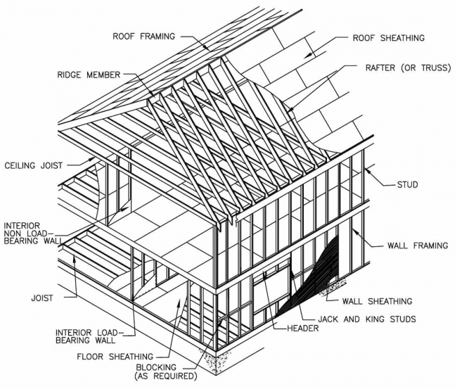
Wood is the most popular material used in the USA for the construction of single-family dwellings. An example of residential framing can be seen below in Figure 2 [ 6 ]. Framing lumber is easily obtained in most locations.
The units of construction can be easily transported by contractors or homeowners without the need for specialized equipment. Additionally, the erection of a wood-framed structural system is familiar to most and does not require excessive amounts of specialized knowledge or tools.
Lastly, wood-framed construction has been well documented in the USA, and many design aids are available. Section view of typical residential wood-framed home. Note: in this figure, a small rectangle with x inside indicates the cross section of wood member, and DBL stands for double. As noted before, much of the wood-framed structural design can be accomplished using design aids. The design professional will typically use these design aids to the greatest extent possible and then perform structural analysis and design for typical wood frame construction details item that is beyond the scope of the design aids.
This is the approach that will be used for this study. The design drawings are shown in the Appendix. The associated detailed calculation is not provided due to space limitation; only the necessary results will be mentioned. External loads must be transmitted to ground through the structural system of the building.
Two main systems are needed to accomplish this transfer properly: gravity system and the main wind force resisting system MWFRS.
The gravity system transmits the vertical loads through a system of trusses, joists, and beams to foundation, which in turn transmits the load to ground, while the MWFRS transfers lateral wind load to foundation through a system of shear walls and flexible diaphragms. It is important to recognize that the ground must be properly prepared and evaluated to ensure good load transfer.
Typically, foundations are placed on virgin soil or engineered compacted fill. All organic materials should typical wood frame construction details removed along with excessive amounts of water. The gravity system in this home starts at the roof and ends in the soil. Vertical loads must have a continuous path to the ground.
Generally, the gravity system in this example consists of OSB sheathing, engineered roof trusses, load-bearing stud walls, dimensional lumber headers, engineered I-joist floor system, engineered wood beams, structural steel girders, and a concrete foundation. The OSB roof sheathing, as illustrated in Figure 3serves to transfer gravity load i.
The roof sheathing also transfers the lateral wind loading through diaphragm action to the structure. Attachment requirements of the sheathing to roof trusses are governed by the greater of the wind uplift force or the shear transfer requirement of the connection.
The sheathing can be used with or without edge support at


|
Steel Horse Glider Brackets Lathe Tools Uses Problem Oak Dowel Rod Wickes Ingles Kreg Jig Hole System Quotes |

AnGeL
23.10.2020 at 22:26:50
StoRm
23.10.2020 at 19:24:58
dj_xaker
23.10.2020 at 21:10:11