Riffle Splitter,Under Shelf Drawer Nz 2020,Furniture Pulls Near Me 10 - Videos Download
Precondition the new filter by forcing approximately 25 mL of organic-free DIW through the filter unit and silver filter. Decant from the top of the stream sample to avoid sediment an additional 70 mL into the graduated cylinder and dispense into the filter unit. Force this aliquot of native water through the filter and into the same mL bottle already containing 30 mL of filtered sample.
Discard filter. NOTE: As suspended-sediment concentrations increase, the volume of sample that passes through the filter will decrease. It may be necessary to filter a smaller volume at step If this occurs, use a smaller sample aliquot 20 or 30 mL and repeat steps 9 through 12 until a sample of mL has been filtered for the DOC analyses. Step 11 then will require an additional 90 mL for the DOC sample. Clean all equipment immediately after use, wrap with aluminum foil, and store in a sealed container sealable plastic bag.
Avoid working and storing in areas where methanol vapors might contaminate the equipment. The filter assembly and any other equipment tweezers, graduated cylinder, and so forth should be routinely cleaned ONLY with organic-free DIW accompanied by an aggressive scrubbing with a nonmetallic brush.
Regular inspection of the filter assembly is important to determine if additional cleaning is necessary. A dirty filter unit or a suspected contaminated filter unit will require additional cleaning. Scrub filter unit with a solution of 0.
Scrub and rinse with organic-free DIW. Remember that three 1-L rinses are more effective than one 3-L rinse. Double wrap the equipment with aluminum foil for storage. Samples collected for chorophenoxy-acid herbicides and carbamates NWQL schedules and use the high-pressure liquid-chromatography HPLC method. These synthetic-organic compounds in stream water interact with sediment particles through sorptive processes; therefore, it is important to separate the solid phase from the sample as soon as possible after collection.
Depth filters made from glass fibers with a 0. Depth filters have a high-loading capacity, making them more suitable for filtering the larger sample volumes 1 to 3 L are needed for organic analysis. More detailed information on filtering samples is found in OWQ technical memorandum The filter support should be made of aluminum, Teflon, or stainless steel with a mm diameter.
All equipment and components should be made of materials that will not contaminate or sorb analytes and are suitable for use with organic solvents such as ceramics, glass, fluorinated polymers Teflon , stainless steel, or aluminum. Do not use the hydrochloric-acid cleaning step for equipment used in this procedure. The following procedures should be done in a clean workplace, free from fumes and dust. The samples processed here should be subsamples directly from the cone splitter.
Rinse the filter, tubings, and the filter support by passing AT LEAST mL of native water through the system; use a precleaned oven baked at C for 2 hours , glass-fiber, 0. Remove the air from the filter support and tubing by opening the vent located on the top of the filter support.
Filter sample without rinsing the bottle. Collect approximately 1 L of the filtered sample for each schedule do not completely fill the bottle; leave about a 2-cm headspace to add conditioner and surrogate. Weigh and record the amount of sample filtered; that is, the total weight minus the tare weight of the bottle. Refrigerate or store filtered sample on ice approximately 4 C for additional processing. Changing Filter Paper High sediment and colloid concentrations can slow the filtration rate by clogging the filter paper prior to achieving the volume necessary for analyses.
Clogging might require changing the filter paper during the filtration procedure. To do this, remove the pump intake line from the stream-water sample bottle and pump dry the filter unit before disassembling. Remove the filtered sample from the filter unit. The unfiltered sample must not come in contact with the bottom half of filter unit while the filter paper is being changed.
Fold the clogged filter in half with tweezers, carefully remove, and discard. Rinse the inside of the filter unit with organic-free DIW. Install a new filter paper and condition prior to continuing the filtration process.
Cartridge Processing Samples collected for analysis of organic compounds must be processed through a solid-phase extraction SPE cartridge within 4 days of collection.
The SPE method utilizes bonded silica, packed into an extraction column, which absorbs specific organic compounds. These compounds subsequently are removed from the extraction column using a solvent. This procedure produces a small sample that is analyzed for selected compounds. This extracted sample can be stored for extended periods of time. Record the precleaned SPE cartridge type, lot number, and weight. Condition the SPE cartridge. Use approximately 2 mL of methanol for schedule and approximately 2 mL of ascorbic acid for schedule Follow with approximately 2 mL of organic-free DIW to remove excess conditioner.
Allow the conditioner and water to flow by gravity through the cartridge. At no time should the cartridge go dry once conditioning has started. If it does, repeat the conditioning process. Maintain the water in the cartridge bed by replacing the water that drains through or by using an on-off valve to prevent the cartridge from draining completely. Condition the filtered sample for schedule by adding approximately 10 mL of methanol using a bottle-top dispenser.
The filtered sample for schedule needs no conditioner. Once the conditioner if any has been added record the weight. Add the surrogate mixture 1. Insert the tip into the sample below the water surface and press the plunger to deliver the surrogate into the sample. Withdraw the micropipette, remove and discard the glass bore. Rinse the orange-colored micropipette tip with solvent methanol.
Cap and swirl the sample to mix. Use a different surrogate and micropipette for each schedule. Teflon tubing. Insert the pump inlet tubing into the sample. Turn on pump and force the air from the line before attaching the SPE cartridge to the outlet pump line.
For schedule , use a female Luer-Loc fitting P to attach the line to the small end of the C cartridge. Invert the cartridge to discard any conditioning liquid remaining in the SPE reservoir. For schedule , use a male Luer-Loc fitting P and a cartridge adaptor to attach the line to the large barrel end of the carbopak-B cartridge.
Collect the extracted water in a plastic 1-L beaker. When extracting is complete, remove excess liquid from the SPE cartridge using a syringe to blow out the water. Record the final weight of the sample in the beaker. Write the sample identification number on the side of the cartridge and store in a mL amber glass vial on ice approximately 4 degrees C.
Clean all equipment after use by rinsing with a phosphorus-free detergent 0. Next, rinse with approximate 30 mL of methanol. Wrap all areas of the equipment that will contact the sample with Teflon tape or aluminum foil and store in a sealable plastic container. Therefore, samples for many constituents must be stabilized by preservation. Some examples of preservative treatment are refrigeration to minimize chemical change caused by biologic activity and the addition of acid to prevent the precipitation of cations.
Below are some examples of bottles, caps, and treatments for various analyses. Every measure should be taken to reduce the possibility of contaminating samples and equipment during the preservation process. A preservation chamber will assist in this effort.
Be sure the outside of the preservative ampules are clean. Bottles that require no preservation should be set aside in the shipping container. Samples collected for nutrient analyses should be chilled only see OWQ technical memorandum The order in which the preservatives are added also should be considered.
Preserve samples that require acids nitric, sulfuric, hydrochloric, and phosphoric inside a preservation chamber. Discard the gloves worn during these procedures along with the ampules.
Wash hands thoroughly. Change processing chambers and complete any other preservation techniques, such as the addition of sodium hydroxide, zinc acetate, or copper sulfate. If any of these bottles or remaining bottles require chilling, place them on ice. Discard the gloves worn during these procedures along with the acid ampules. By following this sequence for sample preservation, the risk of contaminating a sample with the residue of a preservative left in the air or on the gloves is reduced.
Clearly, great care must be exercised in the field to prevent cross contamination. Acid and potassium-dichromate ampules should be stored and transported separately. Dispose of used ampules properly. If there are any questions concerning the correct preservation technique or the proper disposal of used ampules, consult your District Water-Quality Specialist or refer to OWQ technical memorandums The minimum information required is the site identification number, date and time, sample designation bottle type , and schedule number or lab code as shown below: RA SCH or LC A NWQL analytical services request form needs to be included with each sample.
The forms and the instructions for completing the form are available from the NWQL. Be sure to retain the carbon copy of the form. Place all glass containers in padded sleeves or pack in some other suitable manner to prevent breakage during shipment.
Chilled samples need an adequate amount of ice. Good results have been obtained by packing the chilled bottles in a volume of ice equal to approximately twice the volume of the chilled sample.
The amount of ice necessary varies depending on the length of time in transit from field to laboratory and the time of year. Insulated water coolers from 1 to 5 gal in volume make good shipping containers if the integrity of the container is ensured by removing the spigot assembly and sealing with a silicon or epoxy sealer. Larger volumes of chilled samples can be sent in ice chests as long as maximum weight restrictions of the carrier are not exceeded.
Guidelines on shipping samples are discussed in OWQ technical memorandum Samples should be sent to the NWQL on the day collected when possible. The NWQL also prefers to have all bottles for a single sample sent in one container. However, nutrient samples must be sent in a separate container. Unchilled samples can be sent separately from the chilled samples.
Spouts must be sealed. As part of a program to enhance relations with the post office, the laboratory will not return damaged and leaking coolers.
Line each shipping container with a plastic bag. Make sure all bottle caps are screwed on tightly. Place all 1-L glass containers in individual foam sleeves or in a foam box designed for shipping to prevent breakage when samples are sent in coolers. Ice should be placed inside a double plastic bag in the shipping container. During the summer, in particular, the cooler and samples should be prechilled. Pack the samples with fresh ice, at least a volume of ice equal to the volume occupied by the samples, but preferably twice the volume of ice to samples.
Protect the log-in forms and return labels from the ice by placing them in a plastic bag; the plastic bag should be sealed and fastened to the lid of the cooler with tape. The plastic liner bag must be carefully sealed with a wire tie and the shipping container taped shut.
Immediate analysis in the field is required if results representative of in-stream conditions are to be obtained. Water temperature and dissolved oxygen should be measured directly from the stream, and several readings are required in the cross section to obtain a stream average.
Specific conductance, pH, and alkalinity should be measured from a cone-split subsample so that these results will be from the same water matrix as the other chemical analyses. A single field meter that measures specific conductance, water temperature, pH, and dissolved oxygen directly in the stream may be used if stream profiles are performed regularly. These profiles must confirm that the direct in-stream measurements are comparable to the values from a cone-split sample.
Field water-quality instruments, support equipment, and the reagents used for analyses are listed in table 3, in reports by Fishman and Friedman Ward and Hair , and in selected OWQ technical memorandums Maintain an instrument log and review it prior to each field trip. The operation and calibration of all field instruments including back-up meters and electrodes should be checked to ensure that all are in good working condition. Temperature also affects the rate of chemical reactions, biological activity, conductivity, dissolved oxygen, and pH.
Because of possible environmental contamination if broken, mercury-filled thermometers are not acceptable for field use see OWQ technical memorandum The recommended procedure for determining field temperatures is a thermistor, an electrical device made of a solid semiconductor with a high temperature coefficient of resistivity.
Thermistors can be constructed with a high sensitivity, but are subject to a variety of errors. Therefore, the calibration should be checked in the laboratory at several temperatures using an American Society for Testing and Materials ASTM thermometer to ensure the required accuracy. Never carry a mercury-filled ASTM thermometer in the field.
Field measurements of temperature should include both air-temperature and water-temperature readings. Air-temperature readings should be made by placing a dry thermistor in a shaded area protected from strong winds, but open to adequate air circulation. Avoid areas that may have radiant heat such as near metal walls or sides of vehicles. Allow the thermistor to equilibrate 3 to 5 minutes before recording the temperature.
Water temperatures should represent the mean temperature of the stream at the time of observation. A horizontal and vertical cross-section profile will determine the variability, if any, that exists. Streams with highly variable temperature profiles should have several readings averaged to use as the mean and those variations should be documented.
Streams with a fairly uniform temperature less than 2 C variance 95 percent of the time generally will have one measurement that can be made and reported as the stream temperature. Make this measurement by suspending from a weighted line or placing a thermistor in midstream. Shade the thermistor probe to prevent erroneous readings caused by direct solar radiation.
The thermistor should be immersed in the stream for a minimum of 1 minute prior to making measurements. Report all routine temperature measurements to the nearest 0. For special studies where more precision is required, verify the accuracy and report temperatures to the requested precision. Specific conductance is the conductance measured at 25 C and is reported in microsiemens per centimeter at 25 C. The specific conductance of water is determined by the types and quantities of dissolved substances in the water.
Thus, specific conductance indicates the concentration of dissolved solids in water. The specific conductance of water may change significantly with time because of pollution, precipitation, adsorption, ion exchange, oxidation, and reduction.
Therefore, specific conductance should be measured in the field with an accurate conductivity meter. Many commercial conductivity meters are available on the market. All meters come with operating instructions, and users should be totally familiar with these instructions.
The following are some important features and characteristics of a specific-conductance meter: Automatic temperature compensating direct specific-conductance reading. Platinum, carbon, stainless-steel, or gold electrode. Dip-type electrode. Conductivity electrodes must be clean to produce accurate results. Because of the wide variety of electrode material, the instructions provided by the manufacturer should be followed. Rinse the electrode thoroughly with DIW after cleaning.
Prior to every water-quality field trip and again onsite, standards should be used to calibrate the meter and to check meter calibration. Document calibration checks in the instrument log. Used standards should not be returned to the stock container. Calibration and operating procedures vary with meter types and manufacturers.
The procedures described below are generalized steps that should be followed and will apply to most meters used for field measurements: Presoak electrode in DIW at least overnight. Choose two specific-conductance standards that will bracket the expected value of the sample to be measured.
The standards should be approximately the same temperature as the sample to be measured. Use the calibration standard closest to the expected value of the sample to be measured. Rinse the container and electrode with standard. Pour calibration standard into container holding the electrode. Allow a minute or two for equilibration and then discard the standard.
Calibration setting: Pour fresh calibration standard into the container holding the electrode. The electrode should not touch the sides or bottom of the container. Discard calibration standard into a waste container. Rinse electrode and container with the second standard. The second standard will bracket the range of expected stream conductance. Pour check standard into rinsed container holding the electrode.
Allow to equilibrate, and then discard check standard into a waste container. Calibration check: Pour second standard into the rinsed container holding the electrode. This check reading should be within 5 percent of the known standard value. If not, repeat entire calibration procedures.
Electrode cleaning or replacement, a different meter, or both might be needed. NOTE: Switching meter calibration range will require recalibrating. Discard check standard into a waste container and then rinse electrode and container with DIW. Record all calibration information in the instrument log and on the field notes. If a direct in-stream measurement is made, several readings are necessary vertically and horizontally in the cross section to determine a mean value.
Rinse electrode and container with sample water. Pour sample water into container holding the electrode. Allow to equilibrate for a minute and then discard the rinse sample into a waste container. Sample measurement: Pour fresh sample into the rinsed container holding the electrode. Record the specific-conductance value on the field notes. Discard sample into a waste container and then rinse electrode and container with DIW. It is advisable to store electrode in DIW.
Conductivity measurements are reported as specific conductance and are expressed as microsiemens per centimeter at 25 C. Results are reported to three significant figures, whole numbers only. In aqueous solutions, pH is controlled primarily by the hydrolysis of salts of strong bases and weak acids or vice versa.
The pH is expressed in logarithmic units using a scale from 0 to Solutions having a pH of less than 7 are described as acid; solutions with a pH of more than 7 are described as basic or alkaline. Dissolved gases, such as carbon dioxide, hydrogen sulfide, and ammonia, appreciably affect pH. Degasification for example, loss of carbon dioxide , precipitation [for example, calcium carbonate CaCO3 ], and other chemical, physical, and biological reactions may cause the pH of a water sample to change significantly within several hours or even minutes after sample collection.
Some important features of the meters and electrodes include the following: Digital LCD meter readout with 0. Slope correction preferably with percent of slope readout.
Standard BNC electrode connector. Because a large variety of pH meters and electrodes are available on the market, it is extremely important that operators are thoroughly familiar with the instruction manual provided by the manufacturer.
Electrodes must be clean and properly operating to produce accurate results. The liquid junction also must be free flowing, and the electrolyte solution in the electrode must be at the proper level. Because of the variety of electrodes available, follow the cleaning and storing instructions provided by the manufacturer. Never wipe the pH electrode membrane with anything or store it dry check manufacturer's instructions. The standard buffers have values of pH 4, 7, and 10 with a relatively high ionic strength.
Two pH buffers are needed to calibrate the pH meter 4 and 7 or 7 and Because calibration and operating procedures vary with meter types and manufacturers, the procedures described below are generalized steps that will apply to most meters used for field measurements: Remove filling plug on refillable electrodes prior to use.
Use only the solution recommended by the electrode manufacturer when filling solution must be added. The liquid-filled pH electrodes should always be stored upright.
Bring pH buffers to the temperature of the sample to be measured within a few degrees. Apply temperature-correction factors when calibrating the pH meter. Rinse electrode, thermistor, a small Teflon-coated magnetic stirring bar, and a glass beaker with pH-7 buffer. Pour buffer into rinsed container holding electrode, thermistor, and stirring bar. Allow temperature to equilibrate for a minute and then discard buffer into a waste container.
Calibration: Pour fresh pH-7 buffer in the same beaker holding the equipment. The pH electrode must not be resting on the bottom or touching the sides of the container.
Place the beaker on a magnetic stirrer. Measure temperature, remove thermistor, and adjust meter to the temperature of the buffer. With the stirrer on low do not create a vortex , adjust meter reading to the known buffer value at the specific temperature. Discard pH buffer into a waste container. NOTE: Turn pH meter to "standby" or "off" on meters without standby position prior to removing electrode from a solution.
Select a second buffer to bracket the expected stream pH. Use a pH buffer when expected pH is greater than 7 and a pH-4 buffer when the expected pH is less than 7. Always use a pH-4 buffer as the second buffer when titrating for alkalinity. Rinse electrode, thermistor, and stirring bar with DIW. Rinse another clean beaker, electrode, thermistor, and stirring bar with the second buffer pH 4 or Pour second buffer into that container.
Slope adjustment: Pour fresh pH buffer in the same beaker holding the equipment. Measure temperature and remove thermistor. Set meter temperature to the buffer temperature and, with the stirrer on low, adjust slope to the value of pH buffer.
Some meters have separate slope-adjustment knobs, whereas others use the temperature knob. Always refer to instruction manual when uncertain. Repeat steps 3 and 4 to ensure that any slope adjustments did not change the calibration adjustment. This is a check so adjustment should not be needed.
If adjustment is required, repeat the entire calibration procedure. Rinse electrode, thermistor, stirring bar, and container with stream water.
Pour stream water into container holding the electrode, thermistor, and stirring bar. Allow the temperature to equilibrate and the electrode to precondition itself to the sample. Discard sample in waste container. Measurement: Pour fresh sample into the same container holding the equipment.
Measure and set temperature and remove thermistor. Measure pH and record on field notes. Rinse electrode, thermistor, and stirring bar with DIW, and store electrode as recommended by the manufacturer. Measurements of pH are reported in pH units. Results are reported to the nearest 0. In most waters, alkalinity is caused primarily by the presence of bicarbonate HCO and carbonate CO ions. Some noncarbonate contributors to alkalinity include hydroxide, silicate, borate, and organic ligands, especially acetate and propionate Hem, Because bicarbonate and carbonate predominate in most waters, their determination is essential in studies involving carbonate-chemistry and equilibrium calculations.
Degasification, precipitation, and other chemical and physical reactions can cause the concentrations of bicarbonate and carbonate to change significantly within several hours or even minutes after sample collection.
Consequently, field determinations of alkalinity, bicarbonate, and carbonate are needed in addition to laboratory determinations.
The section on filtration describes the proper method. Several methods can be used to determine total alkalinity, bicarbonate, and carbonate. All of the methods involve titrating a water sample with a standard solution of sulfuric acid and monitoring the change in pH as the acid is added to the sample. The presence and quantity of hydroxide if sample pH is The two methods commonly used are the fixed end-point and incremental methods.
Additional information on alkalinity, bicarbonate, and carbonate determinations is presented in OWQ technical memorandum Using sulfuric acid for titration, the sample pH is lowered to 8. This method is not preferred because it is less accurate than the incremental method.
Instructions on the fixed end-point method are given in a report by Sylvester and others see appendix B. Rather than assuming the equivalence points to be at pH 8. The end point also can be determined by plotting the change in pH divided by the change in volume of sulfuric acid added, noting the maximum rate of change of pH per volume of acid added.
The digital titrator can dispense small quantities of acid and is preferred because the Quality Water Service Unit OCALA performs quality-controls on the normality of the titrant used in the digital titrator.
Depending upon the expected alkalinity, select the sample volume and the appropriate strength titrant cartridge, 0. Assemble the digital titrator by placing the titrant cartridge into the titrator and inserting a clear delivery tube into the cartridge. Turn delivery knob to release a few drops of titrant into a waste container from the end of the delivery tube, gently blot any droplets adhering to the end of the tube, and set digital counter to a ZERO reading.
Inspect the delivery tube; if air bubbles are present, continue to turn knob, expelling the acid until bubbles are removed. Always make sure the delivery tube is below the water surface when dispensing acid into the sample.
Record volume of sample that will be titrated on the field notes. Place pH electrode previously rinsed with DIW into sample to be titrated and place beaker on a magnetic stirrer.
Measure temperature, remove thermistor, and set meter temperature to sample temperature. Turn on stirrer and adjust stirring rate to low do not create a vortex. Turn on pH meter, allow reading to stabilize, and then read and record initial pH value. If sample pH is greater than 8. Record pH and digital-counter reading after each addition of acid. Allow 15 to Riffle Shuffle Decks 20 seconds for equilibration between incremental additions. Sample should be gently stirred with a magnetic stirrer or appropriate stirring device.
Allow 15 to 20 seconds for equilibration and record the digital-counter reading. Add acid by small increments 1 to 3 digital units at a time from pH 5. Allow 15 to 20 seconds for equilibration between incremental additions of acid and record pH and digital-counter readings.
Construct a titration curve plotting the digital counts of titrant sulfuric acid as a function of pH. The end points are the inflection points of the curve near 8. An alternate method is to plot the rate of change of pH with the change in digital counts to determine the inflection points as follows: change in pH change in digital count Use the digital count at the maximum rate of pH change that represents the appropriate end points to determine the following: For 1.
The solubility of oxygen in water Knife For Wood Splitter Europe is dependent upon the partial pressure of oxygen in the air, the temperature of the water, and the mineral content of the water. Oxygen passes through a membrane at a rate relative to the partial pressure of oxygen outside the membrane.
When oxygen diffuses through the membrane, it is rapidly consumed at the gold cathode. The consumption of oxygen causes a current to flow through the cell. The current is directly proportional to the quantity of oxygen consumed and can be converted to concentration units. The membrane is permeable to gases other than oxygen; therefore, halogens, hydrogen sulfide, sulfur dioxide, and helium will interfere with the ability of the probe to give correct readings.
Several new methods for determining in-stream dissolved oxygen are equally dependable. Follow the instructions provided by the manufacturer for calibration and measurements when using other methods for determining dissolved oxygen. A more thorough discussion on the principles of the electrometric method of measuring dissolved oxygen is in a report by Wood and in OWQ technical memorandum Probe membranes should be checked for wrinkles and entrapped air bubbles.
If present, replace membrane and electrolyte. Check for leakage of electrolyte around the membrane and the pressure-compensation diaphragm. The gold cathode should be glossy. Membranes will not last indefinitely; if the electrolyte evaporates and bubbles form under the membrane or the membrane becomes damaged or overgrown with biological growth, replace the membrane after flushing the reservoir with potassium-chloride KC1 electrolyte.
The membrane and electrolyte also should be replaced if meter readings become erratic or calibration is unstable. The zero reading on the meter should be rechecked after each membrane change. The method of probe preparation is as follows: Prepare the electrolyte by dissolving the potassium chloride crystals with DIW. Remove the guard around the sensor and then remove the O-ring and membrane. The gold cathode at the probe tip should always be bright and untarnished.
Wipe the cathode with a clean, lint-free cloth or a pencil eraser to clean. Never use abrasives or chemicals. Thoroughly rinse the sensor tip with potassium chloride solution. Invert the probe and fill with potassium chloride electrolyte.
Pump the diaphragm near the middle of the probe with a pencil eraser or blunt tool to remove the air bubbles. Continue filling and pumping until no more air bubbles appear. Some probes have no diaphragm and can be filled simply by adding potassium chloride solution until no air bubbles appear. Remove a membrane from the kit and secure it between the thumb and side of probe near the probe tip.
Add as much electrolyte as possible to the probe tip. Handle membrane only at the edges to keep it clean and dust free. Grasp the free end of the membrane with the thumb and forefinger. With one continuous motion, stretch the membrane up and over the probe tip and down the other side.
Roll the O-ring over the end of the probe. There should be no wrinkles in the membrane or air bubbles trapped under the membrane. Wrinkles can be removed by tugging lightly on the edges of the membrane.
Repeat steps 2 through 8 if wrinkles, air bubbles, or pin holes are evident. Trim off excess membrane and replace the sensor guard. A number of general precautions and procedures should be followed prior to and during calibration of the dissolved-oxygen meter. Recharge dissolved-oxygen meter overnight prior to any measurement. Attach the dissolved-oxygen probe and turn instrument function switch to any operational position for example, REDLINE 1 hour before use to ensure stability of operation.
Leave meter on until final measurement for the day is completed. Ambient-atmospheric pressure is needed for meter calibration and determining dissolved-oxygen percent saturation of the water being measured. Ambient-atmospheric pressure is true atmospheric pressure at station NOT adjusted to sea level. Use a barometer to measure ambient-atmospheric pressure onsite. The calibration of all field barometers should be checked before each field trip. Barometer Calibration Calibrate the barometer with information from the nearest weather station or airport.
The barometric-pressure readings reported by a weather station are adjusted to sea level, however, and must be converted to the elevation of the field site to enable comparison among location readings. Use the following chart to determine the values to subtract from barometric readings reported at sea level.
Elevation Subtract feet millimeter mercury 1, 27 2, 53 3, 79 4, 5, 6, Air-Calibration Chamber in Water The air-calibration chamber is the preferred procedure because it permits calibration of the oxygen meter at the temperature of the water in which the dissolved-oxygen content will be measured, thereby minimizing errors caused by temperature differences.
The calibration chamber also is designed to allow the membrane surface of the probe to be at ambient-atmospheric pressure while in the chamber. Place probe and calibration chamber in stream water 3 to 5 minutes until they equilibrate with the stream temperature. Remove probe and chamber from stream and pour excess water from chamber. Insert dissolved-oxygen probe into the wet chamber. The air inside the chamber should be saturated with water vapor. CAUTION: Be sure that no water can leak into the calibration chamber and no moisture remains on the membrane; this could reduce the rate of oxygen diffusion through the membrane, thereby producing erroneous results.
Place calibration chamber in the water where the dissolved-oxygen content will be measured. Allow 3 to 5 minutes for the temperature of the air inside the chamber to equilibrate with the water.
Read the ambient atmospheric pressure from the barometer to the nearest 5 mm of mercury. Measure temperature in the calibration chamber to the nearest 1.
Use table 4 to determine the dissolved-oxygen saturation value at the measured water temperature and true atmospheric pressure. Interpolate between readings for an accurate correction. Recalibrate if the scale is changed.
After calibration, check the dissolved-oxygen meter and probe in a dissolved-oxygen free solution. If the instrument reading exceeds 0. Thoroughly rinse probe with DIW to remove any residue of the zero-dissolved-oxygen solution. Meter is now calibrated and ready for use. Table 4. Solubility of dissolved oxygen in water at various temperatures and pressures. Weiss Deep Sea Research, v. Air-Saturated Water This method calibrates the dissolved-oxygen meter using water saturated with oxygen at a known temperature and ambient atmospheric pressure.
Use approximately 1 L of DIW or native water. The temperature of the calibration water should be close to the ambient water temperature. Place dissolved-oxygen probe and the calibration water in a large beaker or open-mouth container and allow the temperature to equilibrate. Aerate the water for several minutes 3 to 5. This is most easily accomplished with a small battery-operated aquarium pump and a short section of tubing with a gas-diffusion stone attached. Observe meter while aerating calibration water.
If no change in dissolved oxygen is observed for a period of 2 to 3 minutes, the water can be assumed to be saturated. Measure temperature in the water chamber to the nearest 0. Determine the dissolved-oxygen saturation value at the measured water temperature and true atmospheric pressure using table 4. After calibration, check the dissolved-oxygen meter and probe in a dissolved-oxygen-free solution. Meter is now calibrated and ready to use.
Cross-sectional profiles will help to determine if the stream has a fairly uniform dissolved-oxygen concentration. If the stream cross section has uniform dissolved-oxygen concentrations, a single measurement can be made usually at the centroid of Riffle Web Page flow.
If the stream does not have uniform dissolved concentrations, or if a cross-sectional measurement has not been made, make several measurements and report an average discharge-weighted average is preferred concentration. Dissolved-oxygen measurements should not be made in or directly below stream sections with turbulent flow or in still water near the streambank because these conditions generally do not represent the majority of water flowing along the stream reach.
The dissolved oxygen should be measured with the probe immersed directly in the stream. If the stream velocity is so high that the probe will not submerged, attach the probe to a small weight on a separate line. Turn on the dissolved-oxygen meter to any operational position for example, REDLINE 1 hour before use to ensure stability of operation.
Turn operation switch to the range used during calibration. Read and record the dissolved-oxygen values after the reading on the meter has stabilized at least 2 minutes. Remove the probe from the water, rinse with DIW, and store the probe tip in a storage bottle that contains a damp towel or immerse in DIW. Protect the probe from freezing. Turn the operation switch to the OFF position after the final measurement of the day.
Report dissolved-oxygen concentrations to the nearest 0. Figure 2 shows page 1 of the field notes. Pages 2, 3, and 4 include meter calabration information, quality assurance samples, alkalinity titration summary, and cross-section profile information. Complete all appropriate sections. A complete documentation will aid in future analyses of the collected information. Field notes should include the following information: Station name and number.
Date and mean time. Gage height, discharge, or both; stage conditions. Sampler and nozzle used for example, DH, D Location of sampling cross section for example, bridge, wading. Number and locations of verticals sampled. Compositing and splitting procedure. Field analyses and calibration procedures pH, conductance, etc.
Detailed alkalinity titration. Name of sample collector s. Site information: sampling method and if limits were exceeded, vertical transit rate, color and odor of the stream, weather conditions, and additional information.
Surface-water quality field notes. Establishment of quality-assurance plans ensure that the data collected are compatible and of sufficient quality to meet program objectives.
This field guide and accompanying references, along with the study-unit design guidelines for NAWQA, should be used by the study units when preparing quality-assurance plans.
Specific details for quality- assurance plans are described in a report by Shampine and others Investigators in each study unit must document the quality of their data by collecting quality-control samples.
A series of quality-control samples field blanks, replicates, and field-matrix-spike samples is obtained in water-quality investigations Shampine and others, because the quality of the data collected and the validity of any interpretation cannot be evaluated without quality-control data. Quality- control samples should include the same sample set as the routinely scheduled samples. New Products. Sieve Shakers. General Lab. Scales and Balances. Clearance Product List.
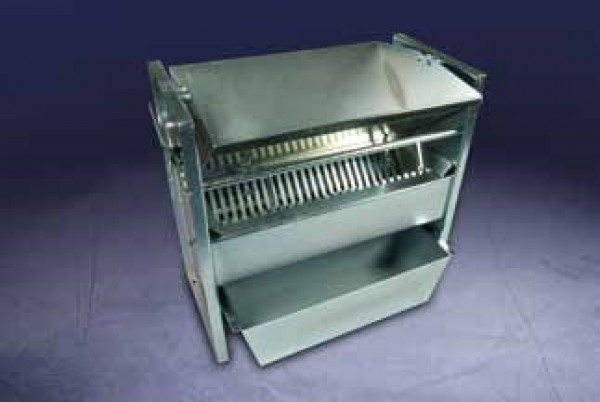
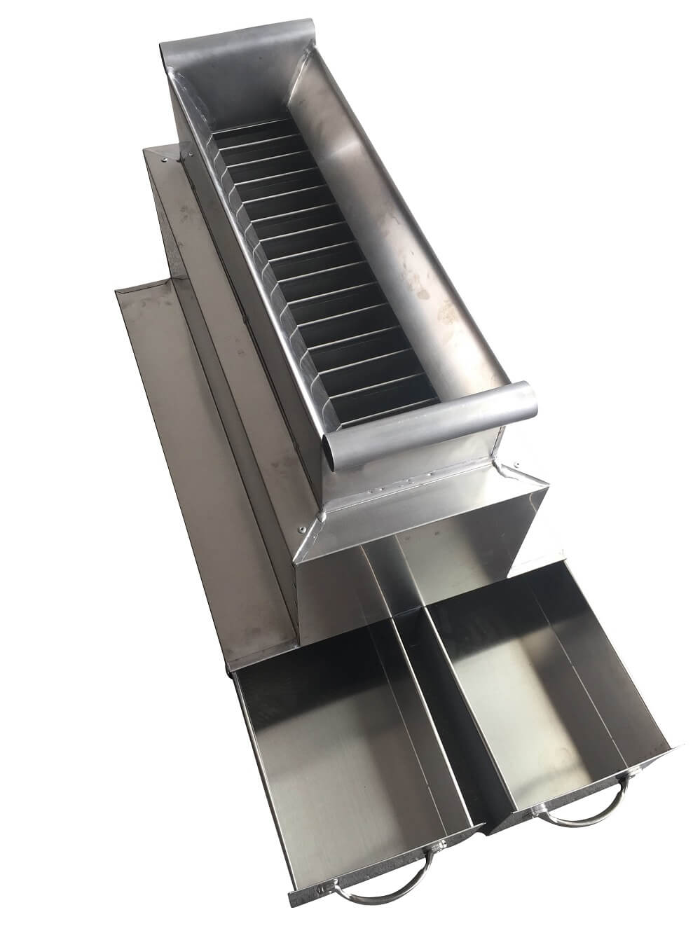
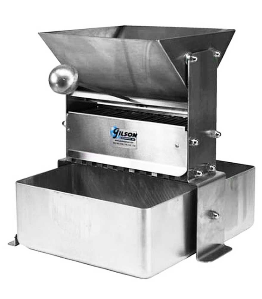
Read More Universal Sample Splitters. Universal Mini-Splitters. Fixed Chute Splitter, 1. Quartermaster Asphalt Sample Divider. Enclosed Sample Splitters. Riffle Splitters. Laboratory Split-O-Matic Splitters. Production Split-O-Matic Splitters. Sample Quartering Kit. Sampling Probes.

|
Kreg Jig Screw Length Name Wood Carving Tool Sets Beginners Vol |

GOZEL1
13.11.2020 at 15:49:10
Dusty
13.11.2020 at 21:20:27
snayper_lubvi
13.11.2020 at 19:44:30