Make A Picture Frame Jig Converter,Best High End Router Table Online,Wood Carving Kits For Sale - PDF Review
While they provided me with this tool, this is not a sponsored post. If you choose to purchase a Kreg Jig through the affiliate links provided, I receive a very small percentage as compensation. Kreg Pocket Hole Jig System. Basically there are 3 adjustments you have to make, which are super fast. This is one of the easiest tools to use and gives you a VERY strong and secure joinery, both if you are joining two pieces of wood adjacently flat, like we are with these frames or perpendicularly like for a box.
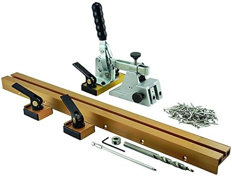
Adjust the jig up or down, to match width of wood you will be drilling into, then tighten screw again. Tighten with wrench again. This is what your pocket hole jig system will look like for these frames. To drill, just place board on the jig, push down clamp, then drill a hole, using a higher clutch speed. Convert to image. Convert to JPG. Convert video to GIF. Convert to SVG. Drop Files here Choose File. Enter URL Back. Please try again later!
Please enter the password with the correct permission. Optional Settings. Change size: Width: px. Height: px. DPI: dpi. Enhance Sharpen Antialias Despeckle Equalize. Deskew: Fix crooked images. Enable Deskew. Info: Please enable JavaScript for this website to function properly. How to convert to JPG? Upload your file. It can be an image, document or even a video. Apply image editing by using the settings. You can change the color, DPI, size, and more optional.
The relative location is the blue dot on the side view. Yellow line indicates the measurement between the rear aprons at the top where the hood hinges bolt on The green lines are the diagonals from rear floor support hole to front frame rail forward hole, projected down on a parallel plane like all plan view dimensions. Basic geometry and the assumption that the angle drawn from between the two holes at the rear of the floor support These two diagonals need to match.
With my bent frame rail, they didn't. Good dimension on my car Your mileage may vary. From the 70 Shop Manual Frame Drawing :. Adam said…. Sure thing. I have some time off the next couple weeks, so I'll take some time and update this post. Unknown said…. No, admittedly, I never went back and dimensioned out the jig. However, I'm not sure I'd recommend using them right out of the box anyway.
If you're doing a project like this, you'll want Make A Picture Frame With Kreg Jig Index to make sure you build it to your car, not mine remember, mine was a little bent. My advice is use the FSM drawings, and my end result as a guide on what a finished product could look like, but build one to spec for your car after you get it checked out on a frame machine. That will tell you if you need to make any other accommodations that the FSM and my dimensions wouldn't have told you.
Sorry, I don't mean to answer with a non-answer, but I think this is really, really application read: car specific. Hi Adam, this blog you've got here is terrific. Thank you for maintaining it. It's very helpful. How were you physically measuring the dimensions in the plan view? They're supposed to be projected onto the datum plane in the side view, how did you do that?
I've had mixed results with a plumb bob. Emile: I used plumb bobs for some and a right angle straight edge and a level for others usually when I was alone and could've used a second set of hands. For the bobs to work, I used light fishing line to tie the Bob to a magnetic hook mount.
This lets the Bob fall to rest perpendicular to the datum. I chose which method to use based on access and repeatability I rechecked each number several times. If I couldn't get a consistent measurement usually due to poor access, hard to reach , I'd use a different approach. Plumb bobs can work but you have to take your time with them. Hi, Adam.
This is Emile again. How did you derive the height of the lower control arm mount holes to the datum plane? Did you just measure your known good side? Out of curiosity, what was your measurement.
Thanks again! Phoenix said…. Hi there, great writeup and it is helping me immensely with my own jig construct but I am curious as to how you measured the location for the LCA jig holes as the only measurement given is to the upper suspension front mounting hole Adam, Not sure if my question is making it to you or not.
Hey, Paul, sorry for the slow response. I keep forgetting to check the comments section and non-Mustang life is pretty hectic lately. The body shop that I took my car to for frame measurements said the back end of the car was in spec and needed no pulling or corrections. There are some dents and all, but they'll just pull those when we're in for paint and body work. So I made sure all the datum points I worked to were from the front leaf spring hole forward.
I did stabilize the rear of the car with a separate jig-like item just meant to hold the car steady, not for actual measurements. If you have work to do on the front and back, you'll need to make a jig that covers the whole diagram.
Phoenix: The LCA mounts are located with several measurements, including one LCA removed and all the other measurements were confirmed on a frame rack at a body shop, so it was easier for me to use the Basically, each point is checked off several known good points somewhere else on the car.
If you're missing a whole Make A Picture Frame With Kreg Jig Reaction front end, it's a little harder, but you start with what you have and work forward. It's all based on having known reference points and then checking new parts in several directions to make sure they're located correctly. Emile: I don't recall the actual number, but I did use all the datum-to-frame rail numbers on the drawings.
I did lots of spot checks of the new passenger side assembly to the original drivers side assembly.
The new assembly matched the old factory original pretty well. The new frame rail assembly was mounted so those measurements matched the drawing, and the good drivers side had been already been verified at the body shop's frame machine and then checked again on the jig to ensure they matched as well. The LCA holes, once mounted, matched on both sides, which says as much about the accuracy of the new frame rail assembly as it does about my jig and measurements.
Adam, I want to thank you firstly for the blog post which has become THE reference point for building my own jig and secondly for taking the time to answer everybody's questions, mine included.
It has been a great help and honestly without your page on how you set up and made your own jig I don't think I would have had the balls to do mine myself.
You have saved me thousands The point of the blog is to show folks who know me why I'm a season behind on Game of Thrones, and to help folks who are doing similar projects. It's nice that the most popular post in the blog so far is the part of the project that I think was the hardest and that I put a lot of thought and effort into.


|
16mm Indexable Lathe Tools Kit Router Table Wing Java Pocket Hole Jig Reno Depot Australia |

ARMAGEDDON
01.07.2021 at 10:56:28
Karinoy_Bakinec
01.07.2021 at 15:12:42
Avarec_80
01.07.2021 at 17:43:39
Reksane
01.07.2021 at 15:46:42