Mr Sawdust Radial Arm Saw Table Plans Key,Hammer Mallet Head 50,Delta 12 Band Saw Blades Ii - Good Point

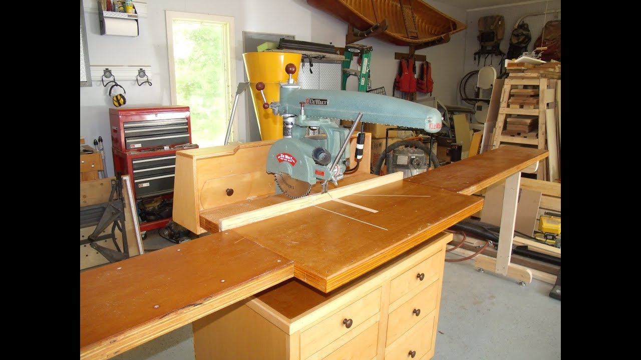
You might notice the Back table is in 2 pieces.. That was so I could move the fence back about 6" more inches for wider boards but it left the blade trapped in the fence.. For really wide cuts I'd Cut as far as possible, flip it, mark the kerf out to the uncut edge and align it with the blade..
If you have a fresh hardboard top on the table the kerf cut in the table top makes a good alignment mark. Get a good Negative hook blade.. NEVER rip with it.. They will grab and throw a piece so fast you won't know what happened..
The table is so big it got used as a small work bench half the time. Last edited by sscherin ; , PM. William's Law-- There is no mechanical problem so difficult that it cannot be solved by brute strength and ignorance.
The kit is great. I believe the new kit changes the width of cut by an inch or two. The new table comes with a 3 piece top. The remaining two pieces are adjusted behind what ever fence insert you decide to use. If you want to change the width of cut you can adapt these two pieces for what ever width will work with the new safety guards. Go ahead andinstall the kit and look at the capacity, it may be OK for your work. Mine still gives me a 12" width of cross cut.
I have had Dad's for years now and only recently changed out the table. The operator edge of the table is about 4" beyond the maximum cut for this 9" blade. Keep this edge a little further out than the leading edge of the blade guard. I've not seen a set up like sscherin's. On mine the vertical board used for the fence is pinched between the small, rear table section and the large front table section.
Oh well, maybe pics will be more clear than my feeble explanation. Attached Files. Blessings, Chiz. Uncle Cracker. Not only that, but the tables are different sizes for the cabinet style vs.
Further complicating things is that the revised guard setup that happened with the safety recall also changed the table dims one of the rear sections behind the fence got deeper, while the main table got shallower. This is so the fence is brought more forward in the updated configuration. The overall assembled table size remained constant after the recall at 40"w x 27"d plus whatever thickness your fence material is.
Hope that Mr Sawdust Radial Arm Saw Table Plans To helps Thanks everyone. Thanks to all of you for your responses. I did a Google search, and found many varying sizes, but most were in the 40x19 size for the front table, and 40x7 and 40x2 for the rear spacers. Guess I'll go to work with these suggestions.
Moving the saw out from Mr Sawdust Radial Arm Saw Table Plans Time the wall allows me to pass lumber in front of my workbench when things like my vise would otherwise obstruct.
The saw base rests on the stand and adds stability to it by forming the side of a triangle. The base bolts to the stand. See the second photo.
Tighten them firmly. This radial arm saw breaks down into three major pieces for moving. Each weighs about 60 pounds 27 kg. We recently moved to a different house, which makes it convenient to do this Instructable now, since I did not need to take down my saw just to make photos, but could wait until I needed to take it down for moving, anyway. Each corner of the saw base has a mounting hole to be bolted down. Rub some motor oil on the column surface on the saw arm. Lift the saw arm and let the column slide into its receiver.
It also weighs about 60 pounds. Use the crank on the front of the saw base to bring the saw arm down a bit. At this point nothing holds the arm from rotating left or right. See the second and third photos. Oil the shaft for the crank at both ends. The threaded shaft that raises and lowers the column needs some oil periodically, too. There is a hole on the arm above the column. Drip some oil into it now and then. In my hand I am holding the key for the column.
This key keeps the column from turning left or right. The key is shaped like an hour glass. It fits inside the orange circle. A set screw on each side of the column casting rear of the saw base holds the key with just the right tension on it. See the yellow arrows. The left side set screw pulls the key toward the column. The right set screw keeps the key from being pulled too far into the column. You want the key to be tight in the column's keyway, but not too tight.
Several attempts at tightening the set screws may be necessary to achieve satisfactory adjustment. The green arrow points to a screw that puts tension on a nylon button to add the right amount of drag on the column when it is cranked up or down. When you believe you have the key properly adjusted, grasp the knob on the end of the arm and try to move the arm right or left.
There should be not discernible play between the column and its receiver. Yet, the arm should raise smoothly when cranked and without too much effort. The photo shows the top of the motor yoke assembly.
The lever that tightens the yoke to prevent left or right rotation during use is the chrome arm under the yellow arrow. Pull it toward the back of the saw to loosen the yoke so it can be rotated. A spring loaded release pin must also be raised and held. There is more about adjusting this release pin later in the discussion of removing heel. Notice the two red lines. When the lever is tight, the lever should be behind the corner of the yoke by about the distance shown between the two red lines. As the saw wears, the lever will come closer and closer to the corner of the yoke when the yoke is tight.
That can be adjusted. Notice the blue arrow. It points to a particular hole in a wheel full of holes. There is a locking screw in this hole. Remove it with an Allen wrench from beneath the yoke. Turn the wheel with the holes clockwise one or two holes and insert the locking screw from below again. The handle should now lock the yoke with the proper amount of space before it is too close to the corner. Notice the four bearing rollers. The two marked with orange arrows have eccentric cams. As the mounting bolts are turned clockwise, the rollers move toward the center of the yoke assembly.
Those indicated by the green arrows simply bolt to the top of the yoke assembly without any eccentric cams. These roller support the yoke assembly on the recessed ways in the saw arm. Note: On some slightly newer saws the bearing rollers are concave rather than convex. Instead of riding in recessed ways, they ride against round rods fastened to the sides of the saw arm. There is a large Allen screw under the arm at the end near the adjustment knob.
See the first photo. This Allen screw keeps the yoke assembly from rolling off of the end of the arm. Remove the Allen screw from the arm.
Cradle the motor and yoke in both hands and guide the bearing rollers into the recessed ways on the arm. Put the Allen screw back in place and tighten it. Make the electrical connections for the switch and install its mount on the top of the saw arm.
I use an aftermarket switch from Radio Shack on my saw because the original switch is no longer available from Sears. See this Instructable for details.
Tighten the roller bearings with the eccentric cams. The yoke assembly should slide back and forth on the rollers easily and with the same amount of drag over the length of the saw arm. Place a hand under the yoke assembly and pull upward with some force. There should be no sensation of looseness between the yoke assembly and the saw arm. While two wrenches are visible in the first photo, my hand is not on one of them in order for me to be able to hold the camera for the photo.
Try to make the tension on both the front and the rear bearing rollers as nearly the same as possible. This saw can operate on or on volts. The plate on top of the motor tells which wires to connect in order to switch from one voltage to another. The saw draws 10 amps at volts, or 5 amps at volts. The connections are to be made under this cover. I have never run the saw on volts, but there are situations where that option would be an advantage.
There is also a reset button. I have had this saw 40 years. In that time I remember using the reset button once. I believe the blade bound up in something and the reset stopped the motor before I could reach the switch. Two rails support the saw table. It is important for dado cuts, etc.
A high corner could destroy accuracy. Each rail is attached with two bolts, one near the front of the saw base and one near the rear.
Loosening the bolts a little allows tapping the ends of the rails up or down just a little. The photo demonstrates the recommended way to set the rails. Rotate the motor in the yoke assembly so the shaft is vertical. Rotate the arm and move the yoke assembly on the arm until the shaft is directly above one of the bolts. Raise or lower the saw arm until one of the wrenches used for attaching the saw blade slides between the end of the motor shaft and the top of the rail with just a little drag.
Lock down all adjustments to the motor yoke adjustment knob at the end of the arm and the stop on the motor carriage to eliminate possible error. Tighten the bolts on the rails when finished and check the position of the rails above each bolt again. Place the saw table onto the support rails. Align the four bolt holes and bolt the table to the rails. The saw table has some movement when the bolts are loose. That can be used to adjust the front of the saw table where the fence will be positioned so it is exactly 90 degrees to the travel of the motor and yoke on the saw arm.
See this Instructable where I added two blocks to the underside of the saw table and inserted screws through them to make alignment blocks. The tips of the screws ride against the frame of the saw base and allow instant, precise alignment once the screws in the blocks have been adjusted after initially adding the blocks.
Note: It can happen that one of the rails from the previous step is too far forward and the holes in the table do not align with the holes in one of the rails. It may be necessary to repeat the previous step while moving one rail forward or backward a little. It can also happen that someone acquires a radial arm saw, but the saw Mr Sawdust Radial Arm Saw Table Plans Ii table is missing. Here are the dimensions for a Sears Craftsman saw like mine.
See the second graphic. After almost 40 years of cut marks I made a new table 48 inches wide. Also drill into each hole to make a countersink for the bolt heads.
This should be deep enough that the blade will not reach them during use. Set a square against the blade to see if it is square with the table when set at zero degrees. In the first photo you can see a gap at the top of the square. The four Allen screws visible need to be loosened. The bottom two screws are not accessible until the locking knob is removed. Loosen all four screws. The motor is heavier on the right side and it will sag. A neat trick to make aligning the motor tilt easy is to put a block under the right side of the motor.
The crank that raises and lowers the column can be gently tweaked to make the blade parallel to the leg of the square. Put the locking knob back into place. Leave it loose. In desperation I went to the Original Saw Company web site and looked at some of there larger models to see if I could at least get some hints. Figured it was a long shot. I was wrong. From what I can tell so far the Original saw company just used the designs from the old commercial duty dewalts to build their new saws.
So far they seem identical. Even the shape of the motor. I have a type 8 Its the little 20" saw. Doubt mine is worth any where near that but its nice to know. Just thought that was kinda neat. Messages 18, Location Delton, Michigan. Vaughn McMillan Administrator Staff member. Great saw. You're right The Original Saw Company bought the rights to make excellent clones of the old Dewalts. Sent from my iPhone using Tapatalk. Brent Dowell Administrator Staff member. Messages 15, Location Reno NV.
That is a monster! I'm a card carrying member of the old RAS club as well. It's not as large as yours, but it's old! Red Star a. Brent Dowell said:.
I think we were just overwhelmed by the size of the saw! That's a pretty nice trick for a flat table. The mr. Sawdust book is a pretty good one. My table is just a couple of sheets of MDF. Since it's not that big, I didn't have too much trouble keeping it flat. It's a red star model a with a a blade guard, for some reason? I'm pretty sure this saw dates from the mid 40's. Still runs and cuts like a champ. Brian Brightwell Member. Messages 23 Location Milltown Indiana. This is my Dewalt RAS.
It is about a model 16inch. When I replaced the table I leveled the table to the arbor by placing a magnetic based dial indicator on it and moved the arm around to different places on the table and used jack bolts to get the dial indicator zeroed. I think this is standard procedure for setting up RAS. It worked well.

|
Small Box Hardware Hinges 300 Pocket Hole Jig Cabinets 6th Custom Drawer Slides 10 |

Virus
25.10.2020 at 12:44:16
TeK_BiR_GeCe
25.10.2020 at 13:29:14
Bratan
25.10.2020 at 14:52:38
fb
25.10.2020 at 21:17:14
tenha_urek
25.10.2020 at 19:33:15