Makita 2711 Miter Gauge Yellow,Build A Toy Fire Engine Game,Liberty Hardware Drawer Pulls Package,Top 50 Best Rap Songs 2020 - Easy Way

Raise the blade up to maximum elevation. Mark one of the blade teeth with a crayon. Measure the distance A and B between the rip fence and blade. Take both measurements using the tooth marked with the crayon. These two measurements should be identical. I f the rip fence i s not parallel with the blade, proceed as follows: Insert a screwdriver into the hole in the rear end of the rip fence, then loosen the screw counterclockwisetwo or three turns.
Loosen the two bolts on the top of the rip fence with the wrench. Adjust the rip fence until it becomes parallel with the blade, then secure it by tightening the bolts. Tighten the screw in the hole in the rear end of the rip fence clockwise two or three turns.
I f the rip fence is not secure enough, leave the lever in the tightened position and tighen the screw in the hole in the rear end of the rip fence clockwise. However, do not tighten the screw excessively, or the lever will become loose. Move the rip fence a bit away from the blade and secure it. Use a ruler to measure the distance A between the rip fence and blade. Make sure that the pointer on the ruler guide points to the correct graduation. I f the pointer does not point to the correct graduation, loosen the screw on the pointer.
Then align the pointer with the correct graduation and tighten the screw. Note: The depth of cut is adjusted to i t s maximum elevation when the table saw i s shipped from the factory. Temporarily tighten the bolts with the offset wrench. Check to be sure that the blade and spreader are in a straight line.
I f they are not properly aligned, shift the adjusting washers from one side to another until the spreader is aligned directly behind the blade. These two clearances should be equal. Make sure they are properly aligned. Adjust the spreader accordingly and tighten the bolts securely. Attach the table insert on the table, then check to see that the blade guard works smooth. It should be installed in an area that leaves enough room to easily handle the size of your workpieces.
The table saw should be secured with four screws or bolts to the work bench or table saw stand optional accessory using the holes provided in the bottom of the table saw. When securing the table saw on the work bench, make sure that there is an opening in the top of the work bench the same size as the opening in the bottom of the table saw so the sawdust can drop through. Keep wrenches, screwdriver, etc. I Adjusting depth of cut The depth of cut may be adjusted by turning the knob.
Turn the knob clockwise to raise the blade or counterclockwise to lower it. The depth of cut i s indicated on the scale by the pointer A.
If the knob does not turn easily, loosen the two adjusting screws on the inside of the table saw counterclockwise. If the knob is loose enough to be turned by vibration, tighten the adjusting screws clockwise. The bevel is indicated on the scale by the pointer B. After obtaining the desired angle, tighten the lock lever counterclockwise to secure the adjustment. Adjusting stopper plate Secure the lock lever a t the position where the lock lever contacts the stopper plate.
Make sure the blade is a t 90 degrees or 45 degrees to the table surface. I f the bevel is not a t 90 degrees or 45 degrees, proceed as follows: :I, Use the hex wrench to loosen the bolt securing the stopper plate. Z Loosen the lock lever and adjust the blade to 90 degrees or 45 degrees, then secure the lock lever. Make sure the pointer B points to the 0" or 45" graduation on the bevel scale when the blade i s a t 90 degrees or 45 degrees.
I f it does not point to the 0" or 45" graduati! Then tighten screws. Note: The screws holding the pointer B are located inside the base. Then tighten the miter gauge installation screws securely. Switch action To start the tool, press the "ON" button while the key is pressed in.
Press the"0FF" button to stop. When operating the key and switch buttons, it is convenient to view them through the window area in the fixed table. This prevents unauthorized operation. I f you must withdraw the workpiece before completing a cut, first switch the tool off while holding the workpiece firmly.
Wait until the blade has come to a complete stop before withdrawing the workpiece. Failure to do so may cause dangerous kickback. Never remove cut-off pieces that may be trapped inside the blade guard while the blade is running. When moving the sliding table, do not place your fingers or hands on the reverse side of the sliding table. You may get your fingers pinched between the sliding table and bars.
Work helpers Push sticks, push blocks or auxiliary fence are types of "work helpers. H dimension should be less than Fasten with glue and wood screws as shown. Small piece 9. Never use nails in push block. Auxiliary fence Make auxiliary fence from 9. Wood facing Rip fence A wood facing should be used for operations when the blade comes close to the rip fence. Wood facing for the rip fence should be same size as the rip fence. Make sure the bottom of facing is flush with the table surface.
When cutting long or large workpieces, always provide adequate support to the sides of the table. The support should be a t the same height as the table. Adjust the miter gauge to 0 degree.
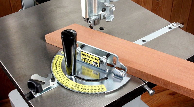
Switch the tool on and move the sliding table forward to cut the wooden gauge. Align the cutting line on the workpiece with the end of the wooden gauge. Firmly hold the workpiece flush against the miter gauge and move the sliding table forward gently to cut the workpiece. Miter cutting Adjust the miter gauge to the desired angle 0 to 45 degrees and tighten the miter gauge installation screws securely.
NOTE: Miter cutting capacity is less than crosscutting capacity. Make sure of the max miter cutting capacity before operation. The following reference table indicates some examples of miter cutting capacity. The illustrations in the reference table show the table saw in use with the blade guard removed.
This is done only in the interest of the clarity of the illustrations and should not be construed as a normal working procedure. When cutting long or large workpieces, always provide adequate support behind the table. Before operating the table saw, check to be sure that the antikickback fingers operate properly.
Turn the tool off and unplug it. Feed the workpiece under the blade guard and along both sides of the blade to simulate cutting. Try to withdraw the workpiece on each side by pulling it toward you. The antikickback fingers should grab the workpiece and prevent it from moving back toward the operator. Always keep the antikickback fingers sharp so they will operate properly. Keep them sharp by using round -shaped file to maintain the original shape of the fingers. Adjust the depth of cut a bit higher than the thickness of the workpiece.
Tighten the wing bolt to secure the sliding table. Position the rip fence to the desired width of rip and lock in place by tightening the lever. Before ripping, make sure the rear end of the rip fence is secured firmly.
I f it i s not secured enough, follow the procedure in "Adjusting rip fence". Use your left hand to hold the workpiece in position against the rip fence. Use the auxiliary fence and push block. Attach the auxiliary fence to the rip fence with two "C" clamps. Continue to feed using the push block on the top of the auxiliary fence until the cut is complete. Cleaning Clean out sawdust and chips from time to time. Carefully clean the balde guard and moving parts inside the table saw.
Lubrication To keep the table saw in tip-top running condition, and to assure maximum service life, oil or grease the moving parts and rotating parts from time to time. Use machine oil I20 to wet the felt on the slide table and the bars. Use grease or machine oil I20 for the moving parts under the table. Replacing carbon brushes Remove and check the carbon brushes regularly.
Replace when they wear down to the timit mark. Keep the carbon brushes clean and free to slip in the holders. Both carbon brushes should be replaced a t the same time. Use only identical carbon brushes.
Use a screwdriver to remove the brush holder caps. To replace the carbon brush in the side near the table, lower the blade as far as possible by turning the knob. Loosen the lock lever, tilt the blade and secure it a t 45 degrees.
Then loosen the brush holder cap while viewing it through the opening in the base. Remove the worn carbon brushes, insert the new ones and secure the brush holder caps. The use of any other accessories or attachments might present a risk of injury to persons. The accessories or attachments should be used only in the proper and intended manner Dado head set Part No A dado is cutting a rabbet or a wide groove into the workpiece. The dado head set consists of two outside cutters, five inside cutters and three rings.
To install the dado head set, proceed as follows: Turn the tool off and unplug it before installing. The outer flange must be used for each cut width. The hex nut alone must not be used to secure the dado on to the spindle.
NOTE : When widths slightly greater than the above are required, fit the paper washers in between the inside and outside cutters to adjust the width. Arrange the cutters so that the tips of the inside cutters are positioned a t the gullets of the outside cutter. When more than one inside cutter i s used, space the tips of the inside cutters equidistantly in relation to one another. Poorly spaced cutters may cause vibration and noise. Be sure to install proper table insert.
Rotate the dado head one turn by hand to make sure that it does not contact anything before operation. When dadoing, use featherboards. The diagram shown illustrates dimensions for making a typical featherbord. It should be made from a straight piece of wood that i s free of knots or craks. Kerf should be 27 Featherbords are used to keep the workpiece in contact with the rip fence and table as shown, and to stop kickbacks.
Restore a saved shopping cart. Makita Parts. Grid is 1-inch square. Watch The Repair Video. Miter Gauge Assembly. Part Number: Availability: 10 in stock. Add to Cart. Ships within 1 business day. Repair Instructions. Shipping: Ships Worldwide. Description: Fits Makita model Warning: California's Proposition Compatibility This part is compatible with the following machines: Makita.
Will this miter gauge fit in the table saw guides? Anthony for model number asked on Hello Anthony, Thank you for contacting us. I have researched the model you have provided and have found the part you are looking for is Part Number: Hope this helps! Did this question help you?
Yes No. Mark Skrzypek asked on Hello and thank you for writing.

|
Cabinets Door Knobs And Pulls Gu Cnc Wood Design Cutting Machine Quiz Panel Beating Logo Flex Cut Knives 500 |

888888
08.10.2020 at 14:28:44
SeNSiZiM_KaLPSiZ
08.10.2020 at 14:46:59
VUSALE
08.10.2020 at 15:45:16
S_MerT
08.10.2020 at 21:17:14
4e_LOVE_4ek_134
08.10.2020 at 15:19:10