Drawer Slide Mechanism Definition Notation,Triton Tra001 Plunge Router Wild,Circle Cutting Jig For Bandsaw Plans Class - Step 1
Allows drawer to open the full length of the slide, providing greater access and making it easier for you to use in general. Full extension slides are ideal for kitchens and any other areas where you might want unobstructed access to the tool you are looking for.
Grooved drawer slides are ideal for a variety of applications where the amount of space in the cabinet and drawer is minimal compared to other formations. Grooved drawer slides are generally intended for living rooms, bedrooms, and home offices, and thus have extremely smooth lateral motion. Handed drawer slides are designed for usage on either the left or right. Unhanded, or non-handed drawer slides can be used on either side and are more popular.
Heavy Duty Drawer Slides. Heavy duty drawer Ball Bearing Drawer Slides Sticking Notation slides range in size from 10" up to 60", with a weight capacity up to lb, lb, and typically up to lbs. Heavy duty drawer slides are commonly used in applications that demand quick access to heavy equipment and tools. Heavy duty drawer slides are commonly found within industrial settings like machinery, safety gates, motion guides, tool box drawers, commercial restaurant equipment, freezers, fixtures for automotive Heavy duty drawer slides range in size from 10" up to 60", with a weight capacity up to lb, lb, and typically up to lbs.
Additionally heavy duty locking drawer slides are commonly used for mobile applications where stability after accessing an item is absolutely necessary.
Thus, heavy duty locking drawer slides can commonly be found in service utility truck beds, fire trucks, SWAT vehicles, expedition vehicles, tool boxes for truck beds, slide outs for recreational vehicle RV basements, trailers, yachts, and other applications that require the drawer stay secure. A hold-in is a type of detent specifically designed to keep a slide closed until you exert enough force to open it.
A hold-out is a type of detent designed to ensure that the drawer is kept open until you exert enough force to close it fully. The distance between the side of the drawer box and the cabinet where the slide is attached. This is often a limiting factor in replacing slides, but is key to calculate when figuring out what kind of slide you will need. Learn more about the importance of installation width from our Definitive Guide to Drawer Slides.
Is the part of the drawer slide between the inner, or drawer member, that attaches to the drawer, and the outer chassis, or cabinet member that attaches to the cabinet itself.
The Intermediate member is essential for keeping the ball bearings functioning smoothly. Keyboard Slide. Working long hours at an uncomfortable work station is an unnecessary evil that too many Americans unfortunately opt for. OVIS offers an affordable and adjustable keyboard tray so that users can quickly and cheaply fix any issues with typing at an uncomfortable desk.
Drawer removal is achieved by releasing a lever and pulling the drawer away from the cabinet. The load rating is the capacity for a slide to withstand a certain amount of weight safely and repeatedly as specified by the manufacturer when fully extended.
Factors such as deflection and dynamic load are used to calculate this figure. A lock-in is the mechanism which keeps a slide locked close until you pull the lever to release it. A lock-out is the mechanism which keeps a slide locked open until you pull the lever to release it.
Over Travel. Over travel, or over extension drawer slides open beyond full extension, giving you total visibility and access for your tools. Over-travel drawer slides are especially ideal in situations where a large countertop or some other ledge might keep you from being able Soft Close Drawer Slide Mechanism Data to full see the contents of the drawer. The slide has only 2 members and as a result has an under-travel because it has no intermediate member. Progressive movement is a result of all slide members moving simultaneously.
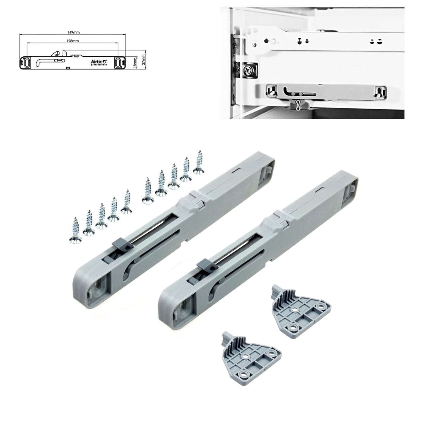
This type of movement provides extremely smooth, quiet movement. The use of shoulder rivets allows the mechanism to be moved, or translated, along the length of the inner slide member. Pushing the mechanism, particularly along a tab 28 at a forward end of the mechanism, causes an end 23 of the mechanism to press against a leading edge 24 of a latch member This results in rotation of the latch member such that stop surfaces formed by a cutout 25 in the latch member do not engage a tab of the intermediate slide member not shown in FIG.
Depending upon the shape of the cutout, or notch, in the latch member, and the amount of push applied, the slide can be closed or disconnected. For example, in one embodiment a forward stop surface, which restricts rearward movement of the slide member, clears the tab prior to a rearward stop surface, which restricts forward movement of the slide member.
Accordingly, greater pivoting of the latch is required to allow the inner member to move forward and disconnect from the other slide members. Further, as illustrated in FIG. In addition, in one embodiment, a register 27 on the mechanism is used to prevent sufficient rotation of the latch through application of the mechanism to allow for sufficient rotation of the latch to allow for disconnect.
Instead, sufficient rotation for disconnect is accomplished by hand. A mechanism 30 can also be designed to activate a spring type latch arm 31 mounted on an intermediate member 39 , as shown in FIG. Such motion results in cutouts of the latch being freed of contact with a tab extending towards the web from another slide member. The spring latch pushes the mechanism back to its original position. The simplicity of the design results in a low cost.
Return action of the release mechanism is provided by the spring qualities of the latch. However, for heavy duty applications or to satisfy a user's preference, a spring 35 can be installed between the mechanism 30 and a lanced tab 36 on the member Beneficially, the spring type latch includes both upper 37 and lower 38 cutouts, thereby allowing the latch and slide member to be used with both right and left hand slides; i. In the embodiment of FIG.
The latch includes a cutout 53 which is adapted to receive a tab extending from another slide member. The latch is bent, as in the embodiment of FIG. The latch also includes a second cutout The second cutout is adapted to receive a protrusion 59 extending from the mechanism. Moreover, in one embodiment, the mechanism also includes a mechanism cutout 57 which is adapted to receive a protrusion extending from the latch.
Pulling a mechanism tab not shown on the mechanism effectively lengthens the latch arm and thereby cause the latch arm to flatten against the slide member. This movement of the latch arm results in the cutout being removed or biased away from the tab. Thus, in alternative embodiments, pulling of the mechanism away from the latch is used to disconnect the latch from a tab extending from another slide member.
The mechanism in various embodiments is thin. Typical construction can be from 16 gauge steel. If the member size permits, the mechanism can be designed to fit inside the shape of the member allowing elimination of rivets. In an exemplary embodiment, the mechanism 20 fits slidably inside the radius 41 of the drawer member 19 as shown in FIG. As indicated, the mechanism is held in place against a web of the slide member through contact with the interior of a bend in the drawer slide forming a bearing raceway.
Thus, in one aspect the mechanism is placed in position, with the bearing raceways thereafter formed as part of a bending operation. Although illustrated in FIG. Moreover, the mechanism is not itself bound by interaction between slide members, as is the latch, thereby increasing ease of operation.
Those skilled in the art will recognize that changes in the shape of the release mechanism and latch can result in different actions. One shape may create release action by pushing, while another cause release by pulling. More refined shapes could allow a release action for closing, but prevent disconnecting of the slide.
Furthermore, although illustrated in a ball bearing slide, the release device will work equally well in slides with roller bearings or of the friction type, with no bearings at all. These slide rails 55 preferably are spot welded at 58 to the bottom of the pan 52 as well as spot welded at 59 to the sides 53 of the pan A downwardly project-ing abutment stop or lug may be bent from the flange 57 of each rail 55 near its outer end for limiting the outward movement of the drawer 50 with respect to the drawer slide cradle 70 described below.
This cradle 70 comprises a pair of parallel channel strips 71 see FIG. Spot welded or otherwise attached or integral with the spanner 72 there are provided projecting up from the front edge of this spanner 72 a pair of U-shaped lugs or stops 74 see FIGS. However, if the drawer 50 is to be removed from the slide cradle 70 it only need have its outer end lifted up so that the stops 60 will clear the top of stops 74 and the drawer then may be pulled out from between the rollers 97 and and removed from cabinet Also on the cradle 70 near the rear of each channel strip 7 1 there is provided the flanged stops 75 mentioned in second I above for cooperation with the pawl stops By lifting the pawls 40 into their dotted line positions 40 as shown in FIG.
If desired additional spanners such as 76 and 77 shown in FIG. At the rear of the strips 71 there may be provided a pair of plastic buttons or glides 78, as shown in FIGS. B Roller Structure and Mountings At opposite corners of each of the strips 71 there are provided a lower fnont supporting roller 81 and an upper rear supporting roller 82 which roll respectively inside the track flanges 32 and of the channel tracks 30 fixed in the cavity 21 in the cabinet These rollers 81 and 82 are attached to the vertical web portions of the channel strips 7 1 by stub shafts 86 and These rollers are preferably made of plastic material molded onto the outside of the frictionless ball bearings.
The plastic may comprise a powdered metal, nylon, Delrin, a polyurathane or similar durable plastic, preferably also reinforced with fibers. The flanges in the channel strips 71 are notched out at their ends 85 and 86 to provide contact for the rollers 81 and 82 with the flange tracks 32 and 31, respectively. In order to support the cradle 70 when it is in its extended position shown in FIGS.
This roller 87, however, is different than the rollers 81 and 82 in two respects. First it has molded thereon adjacent its side an integral gear 88 see FIGS. Thus the major portion 95 of the lever is substantially flush Slide Out Drawer Mechanism Research with the back and front surfaces of the web of the strip 71 and the edges of the lever 98 adjacent its offset portions overlap the extended lower flange portions 96 see FIG. Further in this regard there may be provided a guide member 97 Welded at 98 to the web of the strip 71 for overlapping the offset portion '93 of the lever and prevent it from lateral movement outside of its notch This lever 98 also has mounted on its major central portion 95 near the opposite end from the pivot 91 and roller 87, another roller '97 similar to roller 87 having also molded to one side thereof a gear 98 and pivoted on stub shaft Between the gears 88 and 98 of these rollers 87 and '97 is mounted an enlarged intermeshing gear on a stub shaft also on lever 90, so that both of these rollers '87 and always rotate at the same speed and in the same direction Whether or not both of said rollers 87 and 97 are on the track flange 32 or not.
The pivots or stub shafts 89 and 99' for the rollers 87 and 97, respectively, are mounted substantially in the same plane parallel to the track 32 so that when the drawer is loaded md when both of these rollers 87 and 97 are inside the cabinet 20 they both contact the track 32 and support the slide cradle 70'. The cut out portion 92 for the major portion '95 of the lever 98 reduces the space taken up by the gearing mechanism for the rollers 87 and 97 and any loss in strength caused by this cut out portion 92 is compensated by the wide spanner 72 welded to the lower edges of both strips 71 beyond the side of their cut out portions '92, as clearly shown in FIGS.
Referring now specifically to the roller shown in FIG. Across the top of the forward roller and the tops of both rollers 97 and 87 rest the drawer 58 along its rail flange In order to prevent the weight in the drawer 50 from tilting the drawer up around the fulcrum of the top of roller 81 when it is in any of its extended positions as shown in FIG.
Once the roller 97 rolls off the forward edge 32' of the track 32 as shown in FIG. Thus the weight of the drawer operates a secondary lever "90 so that the continued rolling engagement of the roller 87 with track 32 through gears 88, and 98, positively and continuously drives the roller 97 causing the double thickness drawer flange rail 56 to be pinched against the roller and move the back of the drawer 5'0 beyond the outside edge of the track 32' and outside the cabinet beyond the jamb 27 thereof as shown in FIG.
Thus the further the extension of the drawer 58 beyond the front face or jamb 27 of the cabinet 20 the greater the spacing required between the rollers 87 and 97 and the larger diameter of gear Similarly if less extension is required, the gear may be decreased in diameter. The lever shows an upstanding portion in FIGS. Herein the geared rollers 87 and 97 and gear are replaced by two toothed notched wheels and which are driven together by an inwardly toothed belt , the outer surface of which belt engages the track 32 and flange rail Thus the wheel and belt are positively driven by the wheel and wheel through belt in turn pinches the lower side of the rail 56 to push it up against the roller to insure uniform and positive extension of the drawer 50 beyond the end 32 of the track If more or less extension is required, a corresponding greater or lesser spacing between the wheels and are required and correspondingly a longer or shorter belt Otherwise the operation for the extension of the modified embodiment shown in FIG.
Thus the drawer 58 is carried on the top of the lower rollers 81, 97 and 87 and is prevented from tilting out of the cabinet by the roller on the slide cradle The roller 82 on the upper rear end of the channel 71 of the slide cradle 78 prevents the top of the cradle from rubbing against the top of the channel track 31 when the drawer is extended as shown in FIG.
Accordingly a smooth, uniform travel of a heavy thick front 51 file drawer 50 may be eifected from its completely closed position to its completely extended position beyond the front face of the cabinet 28 so the full length of the drawer 58 may be used without difficulty or without changing the uniform motion of the slide cradle 70 or releasing any of the stops.
While there is described above the principles of this invention in connection with specific apparatus, it is to be clearly understood that this description is made only by way of example and not as a limitation to the scope of this invention. A a pair of parallel channel tracks having 0- shaped cross sections attached to said side walls with their open sides facing each other,. II a drawer movable between said side walls parallel to said tracks from a position completely within said pocket to a position Completely outside of said pocket, I v.
A a pair of double faced rails on opposite sides of said drawer movable parallel to and projecting between the flanged edges of said tracks,. III a slide cradle between said drawer and said chamber comprising:. A a pair of parallel strips movable in said track between said tracks and said rails,.
B spanner means for connecting said strips together around one side of said drawer,.


|
Build A Frame Drum 3d Fine Woodworking Gift Subscription Price |

arkadas
27.09.2020 at 10:41:19
KUR_MEN
27.09.2020 at 12:57:17