Cnc Router Bit For Acrylic,Clamp On Woodworking Vise Variable,Undermount Soft Close Drawer Hardware In,General Finishes Clear Glaze Effects Up - Tips For You

Hood-Daniel urges the CNC user to keep in mind that these are general guidelines. Another tip regarding cutting depth is to set the target depth to be slightly deeper than the true thickness of your material. This ensures a full-depth cut. Carelessly laid-out designs are the bane of both the environment and your dusty garage floor. That saves you time and money.
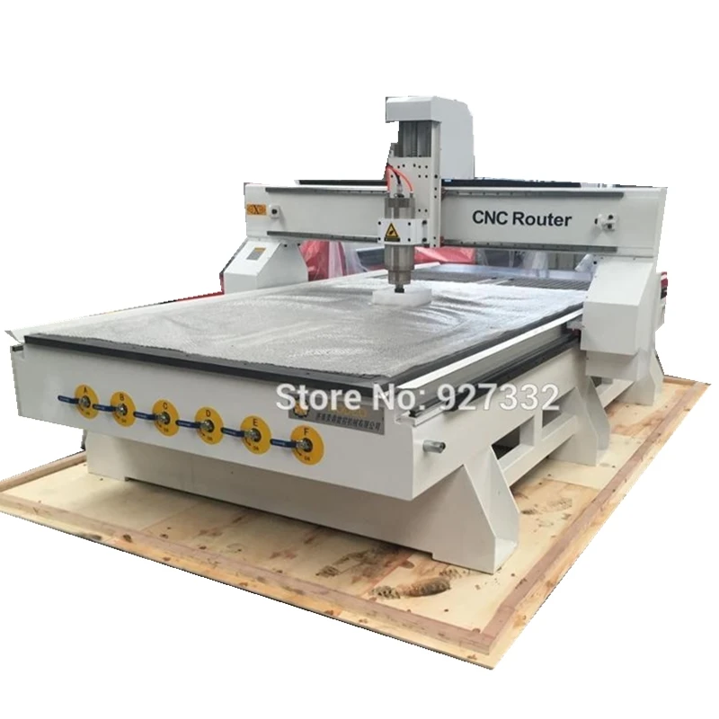
It also lengthens the lifespan of your end mill. Photos: buildyourcnc. She is currently based in Portland, Oregon. Senior Writer Twitter. Topics cnc CNC Mill. Machine bed manufacturing process: The high power machinery requires the body to be precise and stable when working.
Therefore, long-term high power machining should use the casting body to ensure its accuracy and stability. CNC controllers are also generally divided into two types: one type of controller is only driven, and all computing operations are completed by a computer. The computer is in a waiting state while the machine is working, and cannot perform typesetting work. Another type of controller is controlled by a single board computer or a single-chip computer.
This controller is actually a computer, so as long as the machine starts working, the computer can immediately perform other typesetting work, especially when working for a long time, the advantages are particularly obvious. Ball screw and guide rails are also important parts. High quality ball screw and Router Bits For Wood Cnc 50 guide rails are the guarantee of machining precision and performance when the machine is used for a long time.
CNC router machine has three control methods: ordinary variable frequency drive and control, vector control drive and control, and direct torque control. Ordinary frequency conversion is scalar drive and control, and its drive control characteristic is constant torque drive, and the output power is proportional to the speed.
The dynamic performance of ordinary frequency conversion control is not ideal, the control performance is not good at low speed, the output power is not stable enough, and it does not have the C-axis function. But the price is low, the structure is simple, and it is generally used for grinders and ordinary high-speed milling machines. The vector control technology imitates the control of a DC motor, is oriented by the rotor magnetic field, and realizes the drive and control by the method of vector transformation, which has good dynamic performance.
The vector control drive has a large torque value at the beginning. In addition, the electric spindle itself has a simple structure and small inertia, so the starting acceleration is large, and the allowable limit speed can be reached instantaneously after starting. This kind of drive includes open loop and closed loop. The latter can realize position and speed feedback, not only has better dynamic performance, but also can realize C-axis function.
Direct torque control is another new type of high-performance AC speed control technology developed after vector control technology. Its control idea is novel, the system structure is simple and clear, and it is more suitable to drive and satisfy high-speed spindles. Turn on the power of the control computer and monitor, and start the CNC software 2.
Press the power switch. Turn on the spindle motor cooling water pump and check the cooling water flow. If the machine is turned on for the first time today, depress the handle of the lubricating oil injector once, and add lubricating oil to the lubricated part.
Perform the mechanical origin return operation in the software, and eliminate possible collisions before the operation. Manually move each feed axis 1 to 2 back and forth within the full stroke. Step 2, Workpiece Clamping. Place the cushion material in the center of the workbench.
Place the workpiece to be processed on the mat. Use at least 4 sets of pressure plates to fix the workpiece on the worktable. Check whether the workpiece is clamped firmly. Find the edge and set the workpiece origin: 5. Move the spindle along the feed axis that accurately sets the origin until the tool will touch the workpiece. Start the spindle. Switch to single-step movement with step size 0. Move in one step until the rotating tool touches the workpiece.
At this time, a slight noise will be heard. Zero the workpiece coordinates of this axis or record the current machine coordinates. Move the axis to move the tool away from the workpiece, and pay attention to confirm that the moving direction is correct.
Disconnect the power of the routing machine to ensure that the spindle motor Best Cnc Router Bits For Wood 30 stops. Move the spindle to a position where it is easy to change the cutter, and place the soft material directly under the cutter to avoid damaging the cutting edge when the cutter falls. Fix the spindle with a small wrench, and turn the chuck nut clockwise viewed from top to bottom with a large wrench, taking care not to hit the cutting edge with the wrench.
If you need to replace the chuck, unscrew the chuck nut and replace the chuck to remove foreign objects in the machine chuck and chuck nut. Check whether the cutting edge of the router bit to be clamped is intact. Install the collet and nut on the spindle. Insert the router bit to be clamped into the hole of the chuck, as far as possible according to the actual situation but the cylindrical part of the bit cannot be fully inserted , and tighten the nut by hand.
This step cannot be reversed from the previous step: do not insert the bit before installing the nut on the spindle. Tighten the nuts with two wrenches, being careful not to use too much force, and also being careful not to hit the cutting edge with the wrench. Confirm that the wrench is away from the spindle, and turn on the power. Set the router bit again and set the Z coordinate of the workpiece origin.
Confirm the following work: 1. The router bit is firmly clamped. The workpiece origin is set correctly, especially the Z coordinate of the workpiece origin after tool change. Workpieces are clamped firmly. The drive screw is a piece of stainless steel threaded rod M The drive screw is clamped between the two bearings with two nuts.
I drilled and tapped the timing pulley for an M10 thread and just screwed it onto the top part of the drive screw. It is held in place by three set screws. The delrin drive nut gets attached to the Y - axis carriage see step The router mount was pre-made and I ordered it from damencnc. It has a 43mm clamping ring, which fits the Kress router that I am using. If you want to use a water cooled spindle instead as an upgrade, a mount is often included in the kit.
You can also purchase these mounts, if you want to use a dewalt or bosch router with a cylindrical body. I did not want the motors to be sticking out of the machine.
Because this would increase the overall size of the machine by about 15 cm in each axis. Normally you would mount the motors on the outside of the machine using a special motor mount or standoffs. This way you can couple the motors directly to the ball screws with a flexible coupler of some sort.
This is how I did it on the first wooden prototype machine I built. For most people this will probably work out just fine. But what I found was, that because the machine was placed in a very small shop, the motors would really get in the way. Because they were sticking out by almost 20 cm motor standoffs I quite frequently would bump against them.
That is why I placed the motors on the inside of the new machine. By doing this I could not directly couple the motors to the ball screws, but I had to use a timing belt and pulleys. I ordered the timing belts and pulleys from beltingonline. They have a big variety of types and sizes. I used 9 mm wide HTD5 belts and pulleys. When using a belt drive to connect your motor to the drive screw, you can use a gear reduction.
By using a smaller gear on the motor you can use smaller motors and still get the same torque although you will of course lose speed. Because my motors were pretty large I did not need any gear reduction to get more power. To save some money I ordered the timing pulleys without the holes for the setscrews and with only a pilot hole in the centre. I used the lathe to drill out the bore to the correct size.
For drilling the holes for the setscrews, I made a little jig out of some steel hexagonal bar using the lathe and the drillpress. The motor mounts are made from pieces of aluminum tubing. Mine were pre - cut to length when I ordered them, but you can also use a piece of steel tubing and cut it into square pieces.
The motor mounts for the X and the Y - axis, had to be able to slide in and out, to tension the timing belts. If you use a normal coupler to connect your stepper motors, I recommend making or buying some standoffs. I used the lathe to make the slots and to drill a large hole in one face of the mount, but you could also do this on a normal drill press. I started by making a large hole in one side of the mount with a holesaw.
This allows the motor to sit flush with the surface and it also makes sure the shaft is centered. The motor is fastened to the mount with four M5 bolts.
I made four slots, in the other side of the mount, to allow it to slide in and out. I clamped the piece on a special lathe attachment to mill the four slots. The bearing blocks for the X and the Y - axis are made from 50mm aluminum round bar stock.
I cut off four equal slabs, each 15mm thick. I then faced off each side of the blanks on the lathe. After marking and drilling the four mounting holes, I used the lathe again to drill out a large hole in the centre of the blank. I then made the cavity for the bearing to sit in. The bearings have to be pressed in and the blocks get bolted onto the end and side plates.
I drilled and tapped a hole in the end of the ball screws to hold them in place. By inserting a bolt, I could tighten them against the angular contact bearings. The end of the ball screw was turned down on the lathe to 11mm.
This is the part were the timing pulley gets attached to. The very end of the ball screw was turned down a little bit further to 10mm, so that it could be pressed onto the bearing. On the floating end of the ball screws, I just used standard ball bearings.
Instead I used standard, but high quality M10 threaded rod. I made a nut out of a piece of delrin. Inside the Z-axis assembly, there was very little room to mount the nut.
And since my homemade nut was round, I needed to make a special mount. The mount consists of two pieces of 12mm acrylic. I was able to use the homemade CNC router of my school teacher, to make these parts. The round nut fits very snuggly inside the pieces of acrylic and is held in place by a small bolt. The bolt keeps the nut from spinning inside the mount. I drilled and tapped two holes in the little feet of the holders, to be able to mount it to the Y-axis carriage.
For the X and the Y axis, I made a different drive nut mount out of a piece of aluminum. The ballscrew nuts have two small flanges on one side, with three holes in them. I used one of the holes on each side to attach the nut to the holder. The holder is made from a piece of aluminum and is machined on the lathe. These pieces have to be machined very precisely. Once you have attached the nuts to the gantry and Y-axis carriage, you should be able to move these parts easily from one side to the other, by turning the ballscrews by hand.
The Z-axis motor mount is different from the others. It is made from 12mm acrylic and was also cut with the homemade CNC router from my teacher.
I had originally planned to make the mount out of a plate of aluminum, but machining that was too difficult. The belt tension can be adjusted by loosening the two bolts on top and sliding the whole motor mount assembly.
The 12mm acrylic works just fine for now, but I might replace it with a piece of aluminum in the future. I found out that when I was tensioning the belt, the acrylic plate would bend a little bit. The final part I had to make for the machine was the cutting bed.
The cutting bed is a very important part of the machine, and often overlooked. There are many different types of cutting beds. Examples are: t-slot table top, perforated table top, vacuum table or you could just use a disposable table top and screw your stock right onto the table. An aluminum t-slot table top would probably be the best, but it will cost you a few hundred dollars, depending on the size of your machine.
I choose to use the perforated tabletop, because it fitted within my budget and I would still have lots of clamping options. The cutting bed for my machine, is made from an 18mm thick piece of birch plywood.
I fastened it with M5 bolts and t - slot nuts to the aluminum extrusions. I bought about M8 hexagonal nuts for about 4 dollars. Using a CAD program, I drew hexagonal shapes in a grid with a hole in the middle.
Then I used the machine to cut out all of the pockets for the nuts. Instead of regular nuts you could also use T-nuts, but then you would have to flip the tabletop over to insert them.
Another problem you can have is that they fall out. On top of the piece of birch plywood, I installed a piece of 25mm thick MDF. This is the disposable surface. I used a larger router bit, to cut holes through both pieces. The holes line up exactly with the centre of the hexagonal shapes cut earlier.
Then I unscrewed the piece of mdf and installed all of the nuts in the piece of plywood. I made the holes slightly undersized, so I had to use a hammer to pound them in. Then I reinstalled the MDF surface and checked if the alignment was still correct. I also flattened the tabletop to ensure that the surface was parallel to the x and the y axis and perfectly flat. There are a lot of different sellers with prices in the dollar range.
Before ordering a kit you should think about what size steppers you need. I you are building a small machine for cutting wood and plastics only oz in or 1. I choose 3Nm motors, because the machine itself is quite large and heavy and I planned on machining some harder materials like aluminum in the future. Individual drivers can handle more amps and feature microstepping. They are more reliable and will give you better results.
The drivers I use actually came with the kit I ordered. They can handle 4,2 amps max and up to microsteps. The main power supply is connected to the drivers with 14 gauge wire, which is mainly used in RC airplanes.
These wires are very flexible, but of high quality and can handle plenty of amps. The 5 VDC power supply is connected to the main power inlet. For the cooling fans, I installed a power outlet inside of the enclosure, so that I could Cnc Router Bit Set For Wood Key use a standard 12V wall adapter to power them. The main power gets switched on and off by a large power switch.
The 25A relay is controlled by the computer through the breakoutboard. The input terminals of the relay are connected to the output terminals of the breakoutboard. The relay is connected to two power outlets, which power the Kress router and shop vac to suck up the shavings. When the Gcode ends with the command M05, the machine will automatically switch of both the shop vac and the router.
To switch them on you can either press F5 or use the Gcode command M Since I temporarily mounted the electronics on a piece of wood, to test the machine, I still had to make a good enclosure. I drew out the rough dimensions and places for all of the components on a piece of paper. I tried to arrange them in such a way that I could easily get to all of the terminals to install the wires. I also made sure that I would get a sufficient airflow through the enclosure.
This is very important since the stepper controllers can get quite warm. All of the cables can be connected in the back of the enclosure. I used special 4 wire plugs , because I wanted to be able to disconnect the electronics from the machine, without having to unscrew any of the wire terminals.
I also installed two power outlets to provide power to the spindle and a shopvac. The power outlets are connected to the relay to switch the router on and off automatically in Mach3. I mounted a large powerswitch on the front of the enclosure. Once I got all of the components arranged the way I wanted, I designed all the pieces to make the enclosure with a CAD program.
I then used the CNC machine itself to cut out all of the sides and the base. I made a lid with a piece of plexiglas in the middle. I then installed all the components and tried to keep the wiring as clean as possible.
To control a CNC router, you need 3 different types of software. A CAD program, to create a drawing. A CAM program to create the toolpaths and output the G-code. And a controller program which translates the G-code and controls the router. I am using CamBam to create most of my drawings and create the toolpaths. CamBam is a simple program and is very easy to work with.
Before CamBam can create the toolpaths, you need to set a couple of parameters. When you have made the toolpaths, you can output the G-code. The G-code is the machining language, that tells the machine what to do.

:sharpen(1,0,false):quality(100)/product/79/20383/3.jpg)
|
Claphams Beeswax Salad Bowl Finish Best 80s Rap Albums Editor 24 Soft Close Slides 5g Laguna 1412 Blade Size Window |

Hayatim
31.10.2020 at 18:57:54
Stilni_Qiz
31.10.2020 at 11:16:56
Adrenalin
31.10.2020 at 12:32:34
KOVBOY
31.10.2020 at 10:27:32