Band Saw Guard 86,Tattoo Pen Kits For Sale 50,Proving Drawer Under Oven 2020,Bench Vise Quick Release 010 - Reviews

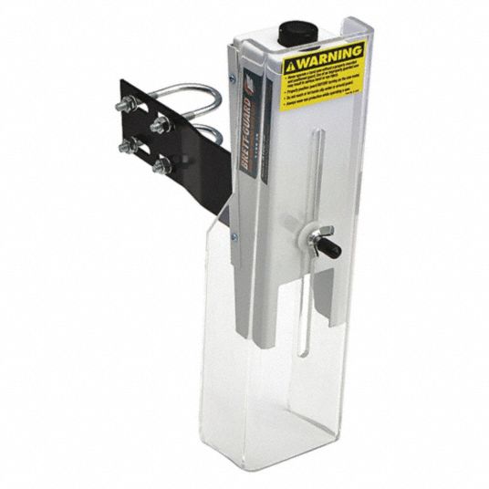
I ordered on line, Staff was easy to work with, Product was everything I Expected. I purchased 2 more, thank you ATS. Email: contact atssafety. Have Questions? View cart. The first bandsaw shown is a 13".
The second one pictured is a 17" bandsaw. The band saw safety guard can mount to the front door using the supplied bracket, or side of the upper housing. Steel adjustable lever for easy re-positioning Shield can flip upward degrees for access.
View full details. Quick look. Choose options. View Details. Customer Reviews. Customer Photos. Reviews Questions. Title of Review.
How was your overall experience? Thank you for submitting a review! Your input is very much appreciated. It is customary to provide protective housings over the driving and support wheels and the rear portion of the band saw blade.
However, because the blade guides must be moved back and forth in order to conform to the various sizes of workpieces, a fixed guard for the blade cannot be used. It is highly desirable to have a blade guard to prevent accidental contact by the operator, and also to protect the operator in case the band saw blade breaks, as occasionally occurs particularly when a strong force is utilized to apply the blade to the workpiece.
It is still further an object to provide blade guards of the type described which almost completely enclose portions of the blade disposed therein on both sides of the workpiece being cut. It is further an object to provide a blade guard so dimensioned and positioned with respect to the blade guides of the saw that the blade can be removed without dismantling the blade guards or blade guide.
It is still further an object to provide a blade guard which moves with the blade guides when they are adjusted. It is an additional object to provide a blade guard of the type described which is relatively simple to fabricate and to mount on a conventional horizontal band saw.
Still other objects will readily present themselves to one skilled in the art upon reference to the ensuing specification, the drawings, and the claims. According to the invention, elongate blade guards are provided having an upwardly open channel and each affixed at one end to one of the blade guides.
The saw blade is completely positioned within the channel defined by the side walls and bottom wall of the blade guards.
The blade guards move with the guides during adjustment. The channels of the blade guides are so dimensioned that the blade can be slipped out of the blade guides, moved downwardly and forwardly between the guides and bottom walls of the guards, and then moved upwardly between the front walls of the guards and the guides, and removed from the apparatus without disassembling either the guides or the blade guards.
Workpiece holders l5 and 16 are mounted on the machine base by means of bolts A horizontal beam 18 is mounted on beam supports 19 and 20 which are in turn affixed to the machine base Adjustable vertical blade guide assemblies 21 and 22 are adjustably mounted on the horizontal beam 18 and comprise, respectively, vertical beam members 23 and 24, upper clamp members 25 and 26 affixed to the beam members 23 and 24, respectively, lower clamp members 27 and 28 affixed to the beam members 23 and 24 by bolts, thumbscrews 29 for clamping the vertical blade guide arm assemblies 21 and 22 to the horizontal beam 18, and trim guards 30 and Affixed to the bottom of guide arm assemblies 21 and 22 are roller guide assemblies 32 and 33 which are similar in structure.
As shown particularly in FIGS. As further shown in FIG. A drive wheel guard 49 is mounted over the drive wheel and affixed to the machine base. A blade support wheel 50 is rotatably mounted on the machine base and is covered by a support wheel guard An endless band saw blade 52 is mounted over the drive wheel 43 and the support wheel A relatively narrow work support plate 56 is mounted on the machine base immediately below the saw blade The blade guards 57 and 58 are so positioned and spacedthat the blade may be removed from its position between the lateral guide rollers, moved downwardly and forwardly to clear the front guide roller, and then upwardly through the space between the forward guide roller 38 and the front wall If desired, the blade guards may be provided with a top wall 66 shown in broken lines and affixed to the rear wall A small space or notch 67 is left intermediate the front wall 59 and the top wall 66 to permit the saw blade to pass therethrough when the blade is removed.
As a result, it is not necessary to remove the blade guards from the vertical guides when removing or replacing the saw blade.
As shown inFIG. Referring to FIGS. A right blade guide assembly 75 is shown mounted on the horizontal beam A similar blade guide assembly, although not shown, is mounted to the left of the guide assembly 75 shown, and has a similar structure includ ing lateral guide rollers and a back-up roller. The right blade guide assembly 75 is also provided with a roller assembly similar to that shown in FIG.
The blade guide assembly 75 comprises a vertical arm 78, an upper clamp member 79, and a lower clamp member 80 affixed to the vertical arm 78 by means of bolts A thumbscrew 82 adjustably clamps the guide assembly 75 to the horizontal beam A trim guard 83 is mounted on the vertical arm As shown in FIG. A saw blade 85 is mounted on the drive wheel, and also mounted on a support wheel not shown on the other side of the apparatus.
A drive wheel guard 92 is mounted on the base A blade support wheel guard is also mounted on the blade support wheel not shown but similar to the structure of FIG. A blade guard 86 according to the invention is affixed at one end to the vertical arm 78 of the guide assembly The other end of the blade guard 86 is telescoped within the drive wheel guard The blade guard 86 comprises a rear wall 87 which is affixed to the vertical arm 78 by screws 93, a bottom wall 88, and a front wall A top member 90 is mounted on the front wall 89 by means of a piano-type hinge In removing the saw blade for replacement or repair, the support wheel for the blade is loosened in conventional manner and the blade removed from the support and drive wheels.


|
Black Filing Cabinet With Lock Cell Dust Collector Malaysia 4d |

K_I_L_L_E_R_0
13.07.2021 at 10:13:57
AXMEDIK_666
13.07.2021 at 18:26:45
232
13.07.2021 at 21:19:55