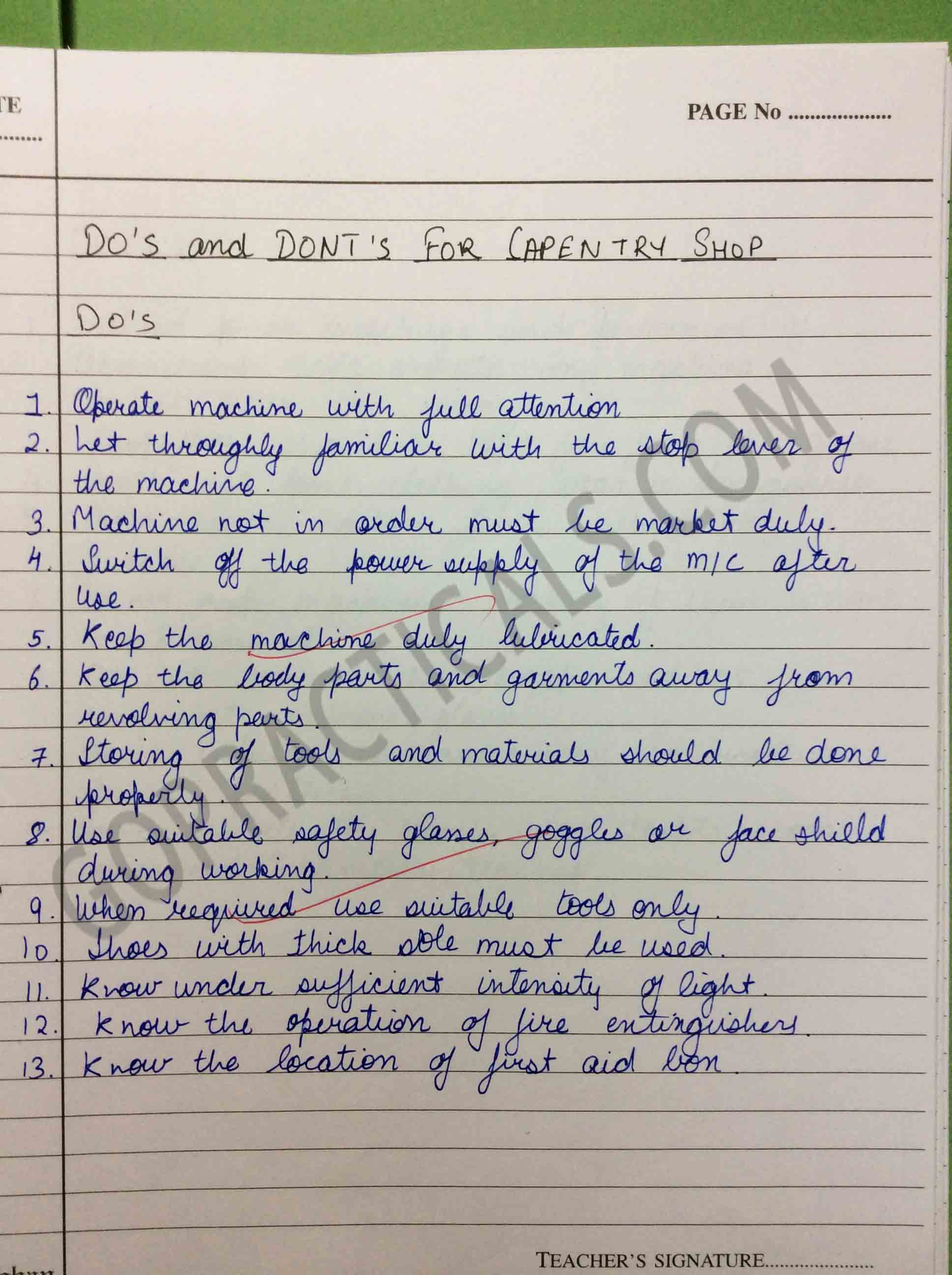
Carpentry Shop Lab Manual Website,Picture Frame Moulding Router Bits Vol,Best Cnc Router Machine 2020 Apk - Plans On 2021
Natural Seasoning a Air Seasoning:In this method of seasoning the sawn timber is stacked in a dry place about 30 cm above floor level with longitudinal and crosspieces arranged one upon another, leaving a space of a few Centimeters for free circulation of air. Advantages i ii iii It does not necessitate much attention It is simple and cheap method.
Less chances of damage to the timber. Disadvantages i Very slow extends over years. By this process, the sap, sugar and gum etc are leached out of the wood and replaced by water.
The logs are then taken out and left to dry in an open places. Advantages It is quick process, tendency of wood to shrink or wrap is reduced less liable to be eaten away by worm or to decay by dry rot. Disadvantages i The process reduces the elasticity and the durability of the timber. Artificial Seasoning a Kiln Seasoning:- The timber is seasoned under controlled temperature and humidity conditions with proper circulation and ventilation system.
The rise in temperature should be such that the timber retains the original strength and elastic properties. The required humidity level is maintained to avoid wrapping and cracking. The drying of timber at uniform rate is well maintained by circulating hot air by fans and a certain amount of steam is added in order to retain correct humidity.
The ventilation is provided to avoid over heating and excessive humidity. The timber inside the chamber , on trolley is kept under controlled conditions for about fortnight or depending upon the initial water content and required moisture level. The quality of wood is inferior as compared to the one seasoned by natural seasoned methods.
Kiln Method The drying is controlled, so no chances for the attack of fungi and insects. The drying of different surfaces is even and uniform. It is costly. More skilled labor required.
Due to quick seasoning so chances to check regularly seasoning defects such as wrapping, internal cracks, surface cracks etc. It is also known as salt seasoning. In the method, the timber is immersed in a solution of soluble salt. It is then taken out and seasoned in ordinary way. The interior surface of timber dries in advance of exterior one and chances of formation of external cracks are reduced.
C Electrical Seasoning:This method of seasoning works on the principle that heat is produced when poor conductor are placed in the field of high frequency. The wooden planks are made to pass through an induction coil producing high frequency.
Due to an induction effect Carpentry Shop Manual Website moisture contents in the wood is dried quickly. This method of drying is employed in plywood manufacturing process. This method is not popular because of prohibitive cost, lack of control moisture content, sudden drying damage wooden fibers.
Electrical Seasoning Seasoning Videos A rtificial seasoning of timber Timber Tress of India 1. The central layer is called core, the outer layer is face plys and intermediate layers as cross bands. It can be made in very large sizes. Easily worked and bend into shapes of different designs. Top veeners can be given fine decorative effects to give attractive appearance.
The strips may be up to about 28mm wide and are placed edge to edge and sandwiched between veneers of softwood, hardwood or thin MDF or particleboard, glued under high pressure. The internal strips are generally made of light weight poplar wood. Blockboard is used to make doors, tables, shelves, paneling and partition walls. It is normally used for interior usages, due to the type of glues used.
To achieve maximum strength, it is important to ensure that the core runs lengthways. Blockboard also called lumber core has very good screw holding and can be considered as solid wood; it has a good resistance to warping.
Types of fiberboard in order of increasing density include particle board, medium-density fiberboard, and hardboard. Fiberboard is sometimes used as a synonym for particle board, but particle board usually refers to lowdensity fiberboard. Plywood is not a type of fiberboard, as it is made of thin sheets of wood, not wood fibers or particles. Fiberboard, particularly medium-density fiberboard MDF , is heavily used in the furniture industry.
For pieces that will be visible, a veneer of wood is often glued onto fiberboard to give it the appearance of conventional wood. These pieces are usually covered with a skin, foil, or fabric such as cloth, suede, leather, or polyvinyl chloride. Fiber Board Battens are used in building construction and various other fields as both structural and purely cosmetic elements.
In the steel industry, battens may also be referred to as "top hats", in reference to the profile of the metal. They are also used on tall ships to form the ladders up the shrouds in a fashion similar to ratlines. They are also used to help secure tarpaulinsover hatches, thus giving rise to the common phrase "batten down the hatches! Used by analogy in non-sailing contexts, it means to prepare to weather a coming storm, whether that storm is metaphorical or real.
Wood Working Hand Tools Classification of tools according to their use is given below Measuring and Marking Tools 2. Holding and Supporting Tools 3. Cutting Tools 4. Planning Tools 5. Boring and Drilling Tools 6. Striking Tools 7. Miscellaneous Tools It consists of a steel Blade fitting into a wooden or metallic stock at right angle to it.
The front edge is hardened so as to resist wear and tear. It is made up of carbon steel. It is used for measuring and marking the points and lines on wooden stock before processing.
Marking Gauge: It is used to draw parallel lines. The movable portion of the gauge is adjustable to suitable position and is tightened on the stem. The piece which slides is called stock and scribing pin is fixed on the stem. Mortise Gauge: It is used to draw two parallel lines.
Its working is similar to marking gauge except it has two sharp edges. One fixed and second adjustable or fixed Bar or T- Clamp and C-Clamp 4. Hand Screw 1. Four carpenter vice are fitted on opposite sides of bench to hold the jobs during operation. Its one jaw is fixed to the side of the table while the other is kept movable means of screw and handle.
Clamps and screws: These are used by carpenters for holding and supporting wood pieces in position for carrying out different operations. Chisels 3. Axe 1. Saws:-Sawing means cutting woods along the grains. The main parts of a saw are blade and handle.
The cope is separated from the drag any loose sand on the cope and drag interface is blown off with the help of the bellows. Now the cope and the drag pattern halves are withdrawn by using the draw spikes and rapping the pattern all around to slightly enlarge the mould cavity so that the walls are not spoiled by the withdrawing pattern.
The runners and gates are to be removed or to be cut in the mould carefully without spoiling the mould. Any excess or loose sand is applied in the runners and mould cavity is blown away using the bellows.
Now the facing paste is applied all over the mould cavity and the runners which would give the finished casting a good surface finish. A dry sand core is prepared using a core box. After suitable baking, it is placed in the mould cavity. The cope is placed back on the drag taking care of the alignment of the two by means of the pins. The mould is ready for pouring molten metal. The liquid metal is allowed to cool and become solid which is the casting desired.
Aim: To prepare a sand mold, using the given Split-piece pattern. Dry parting sand is sprinkled all over the drag surface and on the pattern The sprue base, runners and ingates are also located as shown risers are also placed.
RawFreshly prepared facing sand is poured around the pattern. Result: The required mould cavity is prepared using the given Split Pattern. Step :1 Place Drag part of the pattern on mould board and filled with mould sandStep place cope part of the pattern ,riser, Sprue, runner in position and filled with mould sand. Many products, which fulfill the household needs, decoration work and various engineering articles, are produced fromsheet metals.
Common examples of sheet metal work are hoopers, canisters, guards, covers, pipes, hoods, funnels, bends, boxes etc. Such articles are found less expensive, lighter in weight and in some cases sheet metal products replace the use of castings or forgings. The size of the sheet is specified by its length, width and thickness in mm.
The commonly used gauge numbers and the equivalent thickness in mm are given below The following metals are generally used in sheet metal work: i. Black Iron SheetIt is the cheapest among ail. It has a bluish-black appearance and is uncoated sheet. Being uncoated, it corrodes rapidly. It is prepared by rolling to the desired thickness, then annealed by pleasing in a furnace and then set aside to cool gradually.
The use of this metal is limited Carpentry Shop Lab Manual Free to articles that are to be painted or enameled such as stovepipes, tanks, pans etc. Galvanized IronIt is soft steel coated with molten zinc. This coating resist rust, improves appearances, improves solderability, and improves water resistance.
It is popularly known as G. Articles such as pans, buckets, furnaces, cabinet etc. Stainless SteelIt is an alloy of steel with nickel, chromium and traces of other metals. It has good corrosive resistance. The cost of stainless steel is very high but tougher than Gl sheets. It is used in kitchenware, food handling equipment, chemical plants etc.
Copper It is a reddish colored metal and is extremely malleable and ductile. Copper sheets have good corrosion resistance as well as good appearances but costs are high as compared to Gl and stainless steel. Because of high thermal conductivity, it is used for the radiator of automobiles, domestic heating appliances etc.
Aluminium Aluminium cannot be used in its pure form, but is used in alloy form. Common additions are copper, silicon, manganese and iron. It has many qualities like high ratio of strength to weight, corrosion resistant qualities, and ease in fabrication and whitish in color.
It is used in manufacturing of a number of products such as refrigerator trays, household appliances, lighting fixtures, window work, construction of airplanes and in many electrical and transportation industries. Tin PlatesIt is an iron sheet coated with the tin to protect it against rust. This metal has a very bright silvery appearance and is used principally in making food containers, cans and pans.
LeadIt is a very soft, malleable, low melting point and possesses high resistance to acid corrosion. It is having low mechanical strength so it is used to provide lining to the highly corrosive acid tanks. It is also used in radiation shielding.
A list of them is given below:I. Measuring tools II. Marking tools III. Cutting tools IV. Forming tools V. Joining tools I. Steel rule 2. Vernier caliper 3. Micrometer 4. Sheet Metal gauge The above tools are already explained in the fitting section.
The slots are of various widths and each corresponds to a certain standard wire gauge SWG number. The gauge is placed over the edge of the sheet to be measured and a slot is found that will slip over the metal with a light fit pressure. Standard tables are referred to for conversion of SWG numbers to mm sizes.
Scriber:It is used to scribe or mark line on a metal surface for a variety of purposes. It is a metalworker's pencil 2. Trammel: These are used for drawing large circles and arcs that are beyond the limit of dividers. It has two straight, removable legs tapered to a needle point mounted on separate holders which slide on steel or wooden bar and held in position by thumb screws.
Punches:It is used in sheet metal work for marking on sheet, locating centers. There are two types of punches. These are already explained in fitting section in detail. A snip is a hand shear used to cut thin sheets of gauge size number 20 or above. It works like ordinary scissors. There are several types and sizes of snips available to cut along straight lines or curved lines. Figure a shows a straight snip having straight blades to cut along straight lines.
Figure b shows a bent IV. Stakes:Stakes are the sheet metal anvils used for bending, seaming and forming by using ahammer or mallet. They work as the supporting tool as well as the forming tools. They are madein different sizes and shapes depending upon the job requirement.
Commonly used stakes are Stake HolderThe stake holder used in sheet metal shop is a rectangular bench plate as shown in Figure HAMMERS:The sheet metal is shaped by hammering or striking with mallet, after keeping the work on suitable form of stake. The hammers used for sheet metal work are a Setting hammer, for setting down the edge while making double seam, b Raising hammer for forming curved or hollow shape from flat piece, and c Riveting hammer for riveting purpose.
Mallets are soft hammers used to give soft blows which will not damage the sheet at the same time will shape them. The commonly used types of hammers and mallets are shown in Figure.
The tool has a groove of required width and depth like a die. This groover is placed over the joint double hem or lock seam and hammered from the top of it, to shape the joint that of the groove as shown figure. At the bottom of the rivet set there is a deep hole and a cup-shaped hole. The deep hole is used to draw a rivet through sheet metal and cup shaped hole is used to form the finished head of the rivet-Another hole on the aide of the set is to release the burrs that are punched.
Dollies are used to backup rivets, when it is not possible to support the job on a bench. It is made in various shapes and sizes to suit the use as shown in figure. The purpose of the copper block is to act as a heat source for melting and spreading the solder filler metal at the joining area.
The soldering iron copper is heated using furnace, blower or by electrical resistance. The most common types of seams are as follows Lap seam: This is the simplest seam used in sheet metal work Figure a. This consists of one edge lapping over the other and joint is made by soldering or riveting. Grooved seam: A grooved seam is made by hooking two-folded edges together and then off setting them as shown in Figure 5.
This joint is self-locking and stronger to some extent than lap seam. The edge of the cylindrical part to be joined is slit at short distance and is bent so that alternate pieces come inside and outside of the joint. Permanent joint is obtained by soldering or riveting. Flanged burred bottom seam: This seam is used to fasten the bottom of a container to its body.
The flange of a cylindrical job is often called a burr. The joint consists of a narrow flange which may be joined to inside or outside of the vessel as shown in figure f. Edge FormingFor sheet metal objects strength is given to the edge and the sharpness is eliminated by folding the edge.
The common types of folding used in sheet metal work are as follows:1 WELDINGWelding is a process for joining two similar or dissimilar metals by fusion. The fusion of metal takes place by means of heat. The heat may be generated either from combustion of gases, electric arc, electric resistance or by chemical reaction.
Welding provides a permanent joint but it normally affects the metallurgy of the components. It is therefore usually accompanied by post weld heat treatment for most of the critical components. The welding is widely used as a fabrication and repairing process in industries. Some of the typical applications of welding include the fabrication of ships, pressure vessels, automobile bodies, off-shore platform, bridges, welded pipes, sealing of nuclear fuel and explosives, etc.
Most of the metals and alloys can be welded by one type of welding process or the other. However, some are easier to weld than others. To compare this ease in welding term 'weldability' is often used. The weldability may be defined as property of a metal which indicates the ease with which it can be welded with other similar or dissimilar metals. Elements of welding process used with common welding joints such as base metal, fusion zone, weld face, root face, root opening toe and root are depicted in Figure.
Edge preparations For welding the edges of joining surfaces of metals are prepared first. Different edge preparations may be used for welding butt joints, which are given in Figure. Welding joints Some common welding joints are shown in Figure. Welding joints are of generally of two major kinds namely lap joint and butt joint. The main types are described as under.
Terminology of welding process Lap weld joint Single-Lap JointThis joint, made by overlapping the edges of the plate, is not recommended for most work.
The single lap has very little resistance to bending. It can be used satisfactorily for joining two cylinders that fit inside one another.
Double-Lap JointThis is stronger than the single-lap joint but has the disadvantage that it requires twice as much welding. Tee Fillet WeldThis type of joint, although widely used, should not be employed if an alternative design is possible.
Butt weld joint a. Single-Vee Butt WeldIt is used for plates up to The angle of the vee depends upon the technique being used, the plates being spaced approximately 3. Double-Vee Butt WeldIt is used for plates over 13 mm thick when the welding can be performed on both sides of the plate. Welding PositionsAs shown in Fig. Flat or Down-hand Welding PositionThe flat position or down hand position is one in which the welding is performed from the upper side of the joint and the face of the weld is approximately horizontal.
Horizontal Welding PositionIn horizontal position, the plane of the workpiece is vertical and the deposited weld head is horizontal. This position of welding is most commonly used in welding vessels and reservoirs. Vertical Welding PositionIn vertical position, the plane of the work-piece is vertical and the weld is deposited upon a vertical surface.
It is difficult to produce satisfactory welds in this position due to the effect of the force of gravity on the molten metal. Overhead Welding PositionThe overhead position is probably even more difficult to weld than the vertical position.
Here the pull of gravity against the molten metal is much greater. The basic principle of arc welding is shown in Figure1. However the basic elements involved in arc welding process are shown in Figure2. Most of these processes use some shielding gas while others employ coatings or fluxes to prevent the weld pool from the surrounding atmosphere.
Arc Welding EquipmentArc welding equipment, setup and related tools and accessories are shown in Figure. However some common tools of arc welding are shown separately through Figure.
Few of the important components of arc welding setup are described as under. Arc welding power sourceBoth direct current DC and alternating current AC are used for electric arc welding, each having its particular applications. DC welding supply is usually obtained from generators driven by electric motor or if no electricity is available by internal combustion engines.
For AC welding supply, transformers are predominantly used for almost all Arc-welding where mains electricity supply is available. They Welding cables are required for conduction of current from the power source through the electrode holder, the arc, the work piece and back to the welding power source.
These are insulated copper or aluminum cables. Electrode holderElectrode holder is used for holding the electrode manually and conducting current to it.
These are usually matched to the size of the lead, which in turn matched to the amperage output of the arc welder. Electrode holders are available in sizes that range from to Amps. Welding ElectrodesAn electrode is a piece of wire or a rod of a metal or alloy, with or without coatings.
An arc is set up between electrode and workpiece. Welding electrodes are classified into following types- i Consumable Electrodes a Bare Electrodes b Coated Electrodes ii Non-consumable Electrodes a Carbon or Graphite Electrodes b Tungsten Electrodes Consumable electrode is made of different metals and their alloys.
The end of this electrode starts melting when arc is struck between the electrode and workpiece. Thus consumable electrode itself acts as a filler metal. Bare electrodes consist of a metal or alloy wire without any flux coating on them. Coated electrodes have flux coating which starts melting as soon as an electric arc is struck.
This coating on melting performs many functions like prevention of joint from atmospheric contamination, arc stabilizers etc. Non-consumable electrodes are made up of high melting point materials like carbon, pure tungsten or alloy tungsten etc. These electrodes do not melt away during welding. But practically, the electrode length goes on decreasing with the passage of time, because of oxidation and vaporization of the electrode material during welding.
The materials of non-consumable electrodes are usually copper coated carbon or graphite, pure tungsten, thoriated or zirconiated tungsten. Hand ScreenHand screen used for protection of eyes and supervision of weld bead.
Chipping hammerChipping Hammer is used to remove the slag by striking. Wire brushWire brush is used to clean the surface to be weld. Protective clothingOperator wears the protective clothing such as apron to keep away the exposure of direct heat to the body.
Safety Recommendations for ARC WeldingThe beginner in the field of arc welding must go through and become familiar with these general safety recommendations which are given as under. The body or the frame of the welding machine shall be efficiently earthed. Pipe lines containing gases or inflammable liquids or conduits carrying electrical conductors shall not be used for a ground return circuit All earth connections shall be mechanically strong and electrically adequate for the required current.
Welding arc in addition to being very is a source of infra-red and ultra-violet light also; consequently the operator must use either helmet or a hand-shield fitted with a special filter glass to protect eyes 3. Excess ultra-violet light can cause an effect similar to sunburn on the skin of the welder 4.
The welder's body and clothing are protected from radiation and burns caused by sparks and flying globules of molten metal with the help of the following: 5.
Gloves protect the hands of a welder. Leather or asbestos apron is very useful to protect welder's clothes and his trunk and thighs while seated he is doing welding. For overhead welding, some form of protection for the head is required 8. Leather skull cap or peaked cap will do the needful.
Leather jackets and 1ather leggings are also available as clothes for body protection. Welding equipment shall be inspected periodically and maintained in safe working order at all times. Arc welding machines should be of suitable quality. All parts of welding set shall be suitably enclosed and protected to meet the usual service conditions. All the metals covering frames etc.
Incandescent Light:In candescent means 'glowingat white hot'. A lamp actually work slike aheating element,exceptthat it gives of flight by becoming whiteh ot. The amount of powerit consume sisstamped on the bulb. The higher the wattage, brighterthe light. The bulbs have filaments made of tungsten.
However, special bulbs are available with inside coating and filled with gas. Wires and Wire Sizes:A wire is defined asa bare or an insulated conductor consisting of one or several strands. The wire may consist o f one or several twisted strands. A multi core conductor consists of several cores insulated from one another and enclosed in a common sheathing fig.
Wires ize sare specified by diameter of the wire, using a stand ard wire gauge SWG , which also gives an ideao f the current carrying capacity. Thespecification consist so fb ot htheno. Of strandsand the diameter of each wire in it. Tools and equipment used:6'' cutting pliers, 6''screwdrivers, 1. The process is mainly used for the supply of drinking water and the drainage of waste water, sometimes mixed with waste floating materials in a living or working place.
A plumber is someone who installs or repairs piping systems, plumbing fixtures and equipment such as valves, washbasins, water heaters, water closests, etc. Thus it usually refers to a system of pipes and fixtures installed in a building for the distribution of water and the removal of waterborne wastes. The latin word plumbum, means metal lead pipe, is the origin for developing the term plumbing.
Plumbing process was originated during the ancient civilizations such as the greek, Roman, Persian, Indian and Chinese civilizations as they developed public baths and needed to provide potable water, and drainage of wastes carried by water.
They are usually classified according to the material. They are also grouped as cast, welded, seamless, extruded, etc. For conveying large quantity of water, cast iron, steel or concrete pipes having large diameter are usually used. Galvanized iron pipes GI pipes are popular for medium and low pressure water supply lines.
Plastic pipes are preferred for household uses at low pressure. Pipes are generally specified by their inner diameter Nominal diameter specified in inches. Hence, the pipe fitting size is also based on this dimension.
But for plastic pipes, this rule is not strictly followed because threading is not usually required for them. For engineering uses, along with the nominal diameter, the pipe thickness is also specified as light, medium or heavy. Types of pipe joints:According to the pipe material, size and application, different methods are used to join pipes.
The most common types of pipe joints are Screwed pipe joint -For GI Pipes 2. Welded pipe jointfor steel, copper, aluminum and lead pipes 3. Flanged pipe jointfor cast iron and steel pipes 4. Soldered pipe jointfor brass and copper tubes 5. Glued or cemented pipe jointfor PVC pipes Pipes made of iron GI Pipes and brass of small and medium diameters 10 mm to mm are usually joined by screwing the pipe specials with internal or external threads.
Welding is used to make permanent joint of medium and large diameter steel pipes. The flanged are screwed to the pipe for smaller diameter but made integral for large diameters. Pipes of copper and brass are usually joined by soldering. PVC poly Vinyl Chloride pipe is the most popular choice in plastic group. It is rigid and uses thread and solvent weld glue connections.
It also can be heat fused. PVC pipes are available in various pressure ratings for water supply, and is a very choice for landscape irrigation.
The reasons for the popularity are the economy, no corrosion and easiness to work. CPVC is a different type of plastic, which has an extra chlorine atom in the compound, can be used for the hot water supply, and in industry. To join plastic pipes, gluing or cementing method is used. Solvent cement is the gluing material and it partially melts the surface of the plastic pipe to make the joint.
As the glue evaporates within two minutes, a strong joint is obtained. The term circular saw is most commonly used to refer to a hand-held electric circular saw designed for cutting wood, which may be used less optimally for cutting other materials with the exchange of specific blades.
Circular saws can be either left or right handed, depending on the side of the blade where the motor sits and which hand the operator uses when holding a saw. Drills are commonly used in woodworking, metalworking. Special designed drills are also used in medical and other applications such as in space missions.
The drill bit is gripped by a chuck at one end of the drill and rotated while pressed against the target material. The tip of the drill bit does the work of cutting into the target material, either slicing off thin shavings twist drills or auger bits , grinding of small particles oil drilling , or crushing and removing pieces of the work piece masonry drill. Select the correct size drills, put it into the check and lock it firmly 2.
Adjust the speed of the machine to suit the work by changing the belt on the pulleys. Use high speed for small drills and soft materials and low speed for large diameter drills and hard materials. Layout of the location of the pole and mark it with a center punch. Hold the work firmly in the vice on the machine table and clamp it directly on to the machine table. Put on the power, locate the punch mark and apply slight pressure with the Feed Hand.
Once Drilling is commenced at the correct location, apply enough pressure and continue drilling. When drilling steel apply cutting oil at the drilling point. Release the pressure slightly, when the drill point pierces the lower surface of the metal. This prevents the drill catching and damaging the work or drill. For this, a hole is first drilled, the size of which is slightly smaller than the finished size and then a hand reamer or machine reamer is used for finishing the hole to the correct size.
The Shank end of the reamer is made straight so that it can be held in a tap wrench. It is operated by hand, with a tap wrench fitted on the square end of the reamer and with the work piece held in the vice.
The body of the reamer is given a slight tapper at its working end, for its easy entry into the whole during operation, it is rotated only in clock wise direction and also while removing it from the whole.
A file is hardened steel too, having small parallel rows of cutting edges or teeth on its surfaces. On the faces, the teeth are usually diagonal to the edge. One end of the file is shaped to fit into a wooden handle.
The figure shows various parts of a hand file. The hand file is parallel in width and tapering slightly in thickness, towards the tip. It is provided with double cut teeth. On the faces, single cut on one edge and no teeth on the other edge, which is known as a safe edge.
The figure shows the various types of files based on their shape. A ball peen hammer has a flat face which is used for general work and a ball end, particularly used for riveting. This is used for chipping, riveting, bending and stretching metals and hammering inside the curves and shoulders. It is used for swaging, riveting in restricted places and stretching metals. The blade is made of steel and is available in different lengths and diameters.
The grinding of the tip to the correct shape is very important. A star screw driver is specially designed to fit the head of star screws. The end of the blade is fluted instead of flattened. The screw driver is specified by the length of the metal part from handle to the tip. Types of screw driver 1. It is usually made of forged steel. There are many kinds of spanners. They are named according to the application.
The size of the spanner Keep hands and tools wiped clean and free of dirt, oil and grease. Dry tools are safer to use than slippery tools. Do not carry sharp tools on pockets. Wear leather shoes and not sandals. Do no keep working tools at the edge of the table. Position the work piece such that the cut to be made is close to the vice.
This practice prevents springing, saw breakage and personal injury. Apply force only on the forward cutting stroke and relieve the force on the return stroke while sawing and filing. Do not hold the work piece in hand while cutting. Use the file with a properly fitted tight handle. After filing, remove the burrs from the edges of the work, to prevent cuts to the fingers.
Do not use vice as an anvil. While sawing, keep the blade straight; otherwise it will break Do not use a file without handle. Clean the vice after use. Sequence of operations 1. The dimensions of the given piece are checked with the steel rule. The job is fixed rigidly in a bench vice and the two adjacent sides are filed, using the rough flat file first and then the smooth flat file such that, the two sides are at right angle.
Chalk is then applied on the surface of the work piece. The given dimensions are marked by scribing two lines, with reference to the above two datum sides by using Vernier height gauge, Angle plate and Surface plate.
Using the dot punch, dots are punched along the above scribed lines. The two sides are then filed, by fitting the job in the bench vice; followed by checking the flatness of the surfaces. As the material removal through filing is relatively less, filing is done instead of sawing.
Result The square pieces of 48 mm side is thus obtained by filing, as discussed above. Raw material b. The burrs in the pieces are removed and the dimensions are checked with steel rule. Make both pieces surface levels and right angles by fixing in the Vice, use Files for removing material to get level.
With the help of Try square check the right angles and surface levels. Using Surface plate and Angle plate mark the given two metal pieces as per drawing with Vernier height gauge. Punch the scribed lines with dot punch and hammer keeping on the Anvil. Punch to punch give 5 mm gap.
Cut excess material wherever necessary with Hacksaw frame with blade, Drill bits and Taps. Dimensions are checked by vernier caliper and match the two pieces. Any defect noticed, are rectified by filing with a smooth file. Care is taken to see that the punched dots are not crossed, which is indicated by the half of the punch dots left on the pieces.
Durability: the wire selected should be able the to withstand for a long period against weather changes. Safety: safety is the foremost point to be kept in view while making Decision of the systems of wiring. It may not prove to be risky. At places which are not free from fire danger conduit wiring is preferred. Cost: the cost of wiring installation is one of the main points to be considered.
The system chosen should be economical and within the means of the individual. Appearance: wiring appearance has its own effect. Architectural Beauty should be kept in view. R Vulcanized India rubber wire used in porcelain cleats.
The cleats are of three types, having one, two or three grooves so as to receive one two or three wires. They are made in two halves. One is grooved to receive the wire the other is put over it and the whole is fixed on the wall.
The system of installation is cheap and its most suitable for temporary wiring. It can be easily installed and also removed quickly when not require. It should be free from knots shakes or any other defect. The casing has usually two grooves to carry wires. At the top it is covered by a strip known as the capping.
The width of the capping to show position of wires so that the screws may not be driven through wrong position. Wood gutties are fixed on the wall separated by a distance of not more than one meter. Round porcelain disc insulator are used between the wood gutties and casting. The fixing is done with countersunk scores into the gutties. The capping is screwed over 15cm for all sized up to 6cm. The cable is free the effects of moisture, acids alkalies and climatic variations.
It can be exposed to sun. The system is even suitable for places where chemical fumes are present. This covering provides protection to the cable from mechanical injury.
In residential buildings they are run over wooden battens. The sheathed should be earthed otherwise electrolytic action may take place to the leakage of current and there by deteriorate the covering These cables are not suitable for places where chemical corrosion may rise. They effect on the open ends of cable are give; these cable are more costly than CTS ones. The following points should be noted when installing metal sheathed wiring.
Metal clips and Saddles used to support the cable should be placed 40cm apart. The support used should not be of such a material as to cause chemical action with the sheaths.
The icas sheath should be run over a damp place. The cable should be run over the damp place. The cable should be run in conduits when crossing the floor or wall. Sharp bends should be avoided. Conduit wiring: workshop and public building this is the best and most Desirable system of wiring it provides mechanical protection and safety against fire. They can be supported over the wall by saddles and pipe hooks. VICE: a Vice should not be used as an anvil.
They are specified in length and the range is 15, 20, 25, or 30 cm. Insulated Plier is particular used on live wires because the insulation gives protection from shocks. They are used for taking out or driving slotted heat screws by The size is measured by its blades. A good driver has a hardened and tempered egde. The edge should not be ground to suit different screw heads. POKER: it is a pointed tool with flat sides and used for making pibt holes for screws in wood casing boxes etc.
They are of different length and different diameters. The diameters various steps of 3mm from 6mm to 25mm. Chucks to take drill bits up to 9. Serve the purpose of an Electrician. The numbers are marked on each slot. Holes are provided at the end slot for moving the wire easily. To find the gauge of a wire, the particular slit is found by trail into which a bare wire just slides without being damaged.
The number stamped opposite to the number of the gauge required. KNIFE: it is folding steel knife, which is very useful for cleaning wires.
It should not be used for cutting wires. Usually they are made of steel the tool bits are numbered according to the size of plugs used. Their importance lies in wiring concrete and stonewalls. Holes are made on the walls of sufficient depth and fires plugs are inserted in them.
The material to beheld in position is placed on the plug to expand and grip the wall. While using the tool, it should be rotated slowly after each hammering moreover it Should not be used on the material. SPT Single polo tumbler switch 5 Amps.
Intermediate switch 5 Amps. Batton holder Brass or Bakelite 6. Pendant holder Brass or Bakelite 7. Slanting or angle holder brass Wall bracket 9. Batton holder MC Miniature cup type Wall socket 2 pin 5 Amps. Wall socket 3 Pin 5 Amps Ceiling rose 5 Amps Junction box or cut 5 Amps. Bed room transformer volts.
SWG Standard wire gauge used for expressing the size of wires. Kat 15 Amps. Flexible wire plastic or silk core. Wooden screws 60mm, 50mm, and No. Wooden screws 20mm no 5 for tumbles switches ceiling rose cut out power plug and repair.
Wooden screw 12 mm, no 4 for batton holder Porcelain cleats 2way and 3 way Wood casing and capping Link clips 45mm, 35,, and 30mm etc. Nails 12mm no 17 for link clips. Bare copper wires, no.
The Earth is the biggest negative terminal. In an electric circuit ,if there is any gap due to improper connection, the air being a poor conductor , current will not flow in the circuit. Bur of such a circuit having positive potential is touched by a human being, current will pass through the body into the earth making him a part of the circuit.
Higher the voltage, higher the damage. So the danger of shock is prevented in those countries whereas we have the pro0blem, due to V supply voltage. Ear thing is a safety device to run an electric conductor in parallel to the circuit connecting body of the equipment and a third point to the earth.
By this in case of any open circuit accidentally, the current will travel through the earth wire to earth causing no damage t the person becoming a part of the circuit. It is legally necessary for all machines and other equipment used in factories. FUSE :Fuse is a device to protect electrical equipment against overloading of its components due to short circuits etc. Every electrical If the current supplied is higher, it will damage the equipment.
To prevent such damage a thin wire of low melting point-alloy of optimum current carrying capacity is provided near the main switch in the circuit. If due to any short circuit or voltage fluctuation, the current in the circuit exceeds the limit, the fuse-wire gets melted due to low melting point-alloy with which it is made and the thin dia breaking the circuit.
This saves the electric equipment from getting spoiled by continuous exposure to such high current. The risk is not always apparent, be careful. Take no chance. Always switch off the main switch before replacing a blown fuse. Always use correct size of fuse, while replacing blown fuse. Always maintain earth connection in satisfactory condition, safety depends upon good earthling. Beware of live-wires or conductors bare or insulated.
Before switching on current to any portable equipment, make sure that it is properly earthed and insulation is sound. Be sure that all the connections are tight. Before working on inductive circuits or cable discharge them through short circuit or earth.
Never disconnect a plug point by pulling the flexible wire. Never temper unnecessary with any electrical apparatus unless you are authorized to handle it. Never touch an over head line unless you sure that it is dead and properly earthed.
Never energies a line unless you are sure that all is clean and there is no one working on that line. Never temper with electric prospective or inter-locking gearing unless you are specially authorized for them, taking all precautious. The advices are for your safety only. While handling any portable appliances table fan etc.
When cells are being charged in a room, always maintain good ventilation. Never bring a naked light near a battery. Do not bring a naked light near a battery, Smoking is also prohibited in the battery room. Rubber mattresses are placed in front of electrical panels and switch boards. Do not tie the wire with electric pole.
In case of fire: i Do not throw water on equipment. It will be very harmful to you, because water is good conductor of electricity.
Use portable insulated hand lamp for testing purpose. Pipe 3 Nos. WAG P. Pipe according to circuit diagram. Complete the wiring as per the circuit diagram and check it with mugger before giving the supply. Route Diagram Circuit Diagram Earthing Exercise-4 b To ensure that all exposed conductive parts do not reach a dangerous potential. To maintain the voltage at any part of an electrical system at a known value so as to prevent over current or excessive voltage on the appliances or equipment.
To provide protection against static electricity from friction Concept of Earthing Systems All the people living or working in residential, commercial and industrial installations, particularly the operators and personnel who are in close operation and contact with electrical systems and machineries, should essentially be protected against possible electrification.
To achieve this protection, earthing system of an installation is defined, designed and installed according to the standard requirements.. Figure 1 shows a hacksaw commonly used, it essentially consists of a frame, Handle, Prongs, tightening screw and nut.
The blade is fixed in position and tightened by means of the tightening screws. It has a handle have the length to a suitable leverage, front position is like the letter C, Three rollers are fixed in it. The shape of the rollers is convex on both sides. They are made of alloy steel hardened and tempered. They rotate themselves with friction while moving around the pipe. The third daily block is pressed by means of hydraulic jack and bends the pipes according to the requirements.
Dies are available in different sizes and each one will form thread of that specify size i. Dies are fixed in die holder and pipe to be threaded is fixed in pipe vice. Dies are inserted on to the pipe and die holder is gradually rotated completely till the threads are formed on the pipe.
It is required to check with the help of socket whether thread is completing formed or not. Die holder has to be rotated in opposite direction for withdrawing the die sets form the pipe. It can be rotated in the regular direction partially and dies also rotate. It can be rotated in opposite direction in which ratchet slips and only holder is rotated but not die sets. Again it For withdrawing die sets, ratchet position is reversed so that it rotates the die set in the opposite direction and slips in the regular direction.
Thus die sets are withdrawn from the pipe. These pipes wrenches are manufactured from 50 to 60 cm length. The teeth are provided on the jaws to hold the pipe in position and prevent its slipping while tightening.
After fixing the chain around the pipe, the chain end is inserted in a box for locking with a pin, It holds the pipe firmly and it is fit for rotation on either ways. It is used for screwing and unscrewing of small diameter pipes.
It can also be used in tightening of nuts of bolts, fixing of small taps, valves, etc, in the pipe lines. It is used in house plumbing work. It is the most tool used in the plumbing work. As pipes are made in standard lengths, and desired length of a pipe may be obtained by joining them.
The type of joint used depends upon the material of the pipe and purpose for which it is used. Generally, pipes are made of cast iron, wrought, iron, steel, brass or copper.
The material selection is based on the nature of the fluid to be conveyed, viz. Now a days PVC Polyvinyl chloride pipes are extensively used ease for various purpose.
It is used to join two pipes of the same diameter on a straight line, on any length of pipes. It has inner threads in the both ends to a short length.
The two pipes are screwed in it is any length. It accommodates three pipes at any length. It accommodates four pipes at any length. It has a square neck for a spanner to rotate for tightening or loosening. After tightening the pipes on both ends the octogen nut is tightened. It is used in the pipe line only to separate the connections without disturbing the pipe line. The fluid may be stopped or allowed in any quantity according to the rotation.
This also makes possible leakage proof system. They can be easily transported, handled fixed and maintained. In mines and vent lines in drainage systems.
In Industries, Chemical Plants, Dairies… as chemical waste lines or overflow lines ……. Distribution of water in agricultural fields……. Galvanized Iron Pipe is fixed in the pipe vice and cut to the required length.
The two set screws are adjusted such that the pipe slightly enters into the die set. The threads so formed are known as British Standard pipe BSP threads in accordance with the die set used. The thread length is approximately equal to the die width.
Description Quantity 1. Description 1. Pipe Wrench 4.


|
Saber 375w Belt And Disc Sander Bds46sabs2 Review Api Lowes Kreg Pocket Hole Drill Bit On Rockwell Delta Radial Arm Saw 33 267 Github |

Naina
22.06.2021 at 17:27:26
Karinoy_Bakinec
22.06.2021 at 23:55:46