Acrylic Router Templates Review,Stainless Steel Bottom Mount Drawer Slides Lyrics,Countersink Tool For Wood Industries - Tips For You
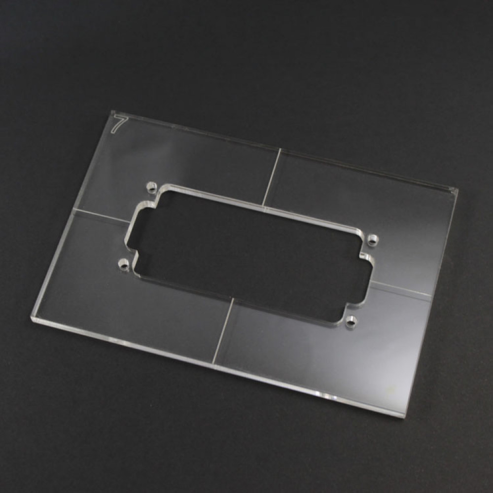
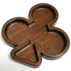
Pumpkin AcrylicTemplate. Size: Requires router bit B Daisy Flower Acrylic Template. Size: Approx C Peace Sign Acrylic Template. D Square Tray Acrylic Template. E Double Heart Acrylic Template. F Maple Leaf Acrylic Template. Size: 12" x 12". G Rectangle Tray Acrylic Template.
Size: 9. Size: 13" x 20". I 4 Section Tray Acrylic Template. J Four Bowl Acrylic Template. Size: 10" x 10". K Single Heart Acrylic Template. Size: 12" x Size: 14" x 14". M Bells Acrylic Template. Size: 16" x 12". N Snowman Acrylic Template. O Christmas Tree Acrylic Template. P Candy Cane Acrylic Template. Size: 9" x 14". Q Stocking Acrylic Template.
Size: 13" x 9". U Santa Hat Acrylic Template. Size: 12" x 13". Y Angel Acrylic Template. Z Gingerbread Man Acrylic Template. Size: 18" x 10 " Requires router bit T Flame Acrylic Template - Video! Templates will not warp or distort. Includes 4 Section acrylic template , Square acrylic template and Paw Print acrylic template Easy to clean! Hearing protection is recommended for extended periods of routing.
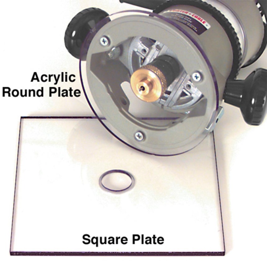
If a vacuum system is not used, a respirator or dust mask will offer protection from dust particles. Prototype and replacement parts can be produced using a hand router. The router is guided around a precut template pattern that is fastened to the acrylic sheet. The template is typically held to the sheet using vacuum or two-sided adhesive tape. Clamps may also be used to hold the template to the material and moved when necessary.
Templates can be made from plywood, fiberboard or rigid plastic. A hand-held router can be piloted around the pattern in several ways. Offsets can be calculated making allowances for the router subbase, template guide, or a piloted bearing follower bit.
Circles of varying diameter can be fabricated with a cutting fixture consisting of a fixed position router and a sliding adjustable rotary table. The adjustable table is mounted on a sliding shaft and column. This can be adjusted for variable center distances.
The sheet is held on the rotating table with vacuum. This method allows for easy machining and size adjustment. It can also be adapted to machine other shapes by following a pattern. Circles can also be cut using a hand router and precut circle templates. Pin routing machines are very versatile. Pin routers utilize a horizontal column to support a pneumatically activated guide pin.
This pin is set directly over a spindle which holds the router bit below the worktable. Both the pin and router bit are fed to a preset stop and are activated by a foot pedal. Plunge routing can be accomplished using this feature. The template has the material to be machined fastened below it. An operator feeds the template along the table to the pin and then guides the top edge of the template along the pin. The material is commonly fastened to the template using double-stick tape or vacuum.
Overhead routers work in the same manner with the router and pin location inverted. Pin routing machines may also be used for multiple part, stepped, or contoured part manufacture. To accomplish this a contour jig must be employed. The desired pattern is cut on the base of the contour jig to match a depth stop preset below the worktable. Several pieces of material are secured to each other to form a stepped template. The cutting tool is then guided by a series of step pin stops set below the worktable.
These pins control the cutting depth of the router bit. The process does not cut all the way through the sheet. The material is only separated following the final cut. This multi cut process enables the cutting of contoured patterns. The ability to remove chips and keep the sheet cool while cutting is a key consideration when engraving.
In general, chip loads IPT of 0. Machines will vary in performance so this information should only be used as a starting reference. In order to optimize machining on a CNC router, there are several key points to consider. The first is the machine type and condition. This includes the integrity of the spindle, the selection and condition of the collets, the machine table and the fixturing. The quality of the equipment and fixtures being used will have a significant impact on the rate at which parts can be processed and the quality of the finished parts.
Fixturing or part hold down will change with the part design and size. The most common way of holding material on a CNC routing table is by using vacuum to hold parts onto a spoilboard base. Spoilboard is a medium density fiberboard MDF that can be machined or milled to facilitate part hold down. Other methods of part hold down include: bolting down the material, using cam lock clamps, and holding the work in a vice that is bolted to the router table.
The part requirements and how they impact processing must be considered. Knowing the depth of cuts to be made, the minimum inside radius required on the finished part, and the edge finish quality requirements will guide the selection of tooling and processing parameters.
Typical processing parameters will include the number of tool bit passes chosen to complete the part and whether or not the part needs to be roughed to shape before finishing passes are made to achieve the desired finish. Machine horsepower and work hold-down or fixturing are the two factors affecting the amount of material that can be removed during each cutter pass.
When multiple passes are required, start with a large diameter roughing cutter to remove the bulk of the material. In most cases, two cutters are used to machine parts to shape, one for roughing and one for finishing.
In some cases, three cutters may be required to complete the part and achieve the desired edge finish and inside radius. For determining the depth of cut DOC to make on each pass, the following guidelines can be used:. Use a material removal ratio of For example if the cutter diameter is 3", then a 2" cut is the maximum depth of material that can be removed per pass. Start with a 0. Note: The cutter edge length CEL listed by the cutter manufacturer may be fully engaged as required. Many single flute up-spiral and center cutting bits can be plunged or programmed to ramp in and take the full cutter diameter for slotting and part cut out.
The DOC for a finishing pass should be no less than. Once the optimum processing parameters have been determined, consideration must be given to the operating conditions for the CNC router.
This includes settings for the spindle speed and cutter feed rate through the material. Routers rotate clockwise when viewed from the spindle or colleted side of the router.
This is also referred to as Right Hand Cutting. If a hand held router is fed into the sheet in a clockwise direction, the cutting edges of the bit will pull the bit into the work rendering control nearly impossible. This routing method is referred to as Climb Cutting. Climb Cutting should only be used on machinery that has rigid spindles and worktables that are free of leadscrew backlash. Climb Cutting will improve product surface finish and increase tool life. Note: This type of machining can only be done on CNC machinery.
Climb Cutting is not recommended for most routing applications. The feed direction for external cuts should be counterclockwise. When routing inside edges, the router should be fed clockwise. This practice will allow an operator to maintain proper control of the router and attain a smooth edge.
This method is referred to as Conventional Cutting. Note: Conventional Cutting is the recommended method for most routing operations. Refer to the routing direction at the top of this page. Slotting, routing shapes out of a sheet, periphery routing, and cutting a part by machining around the outside edge of the part, employ both conventional and climb routing. Care should be taken in the machining techniques and programs to allow for the desired finish.
It is of the Acrylic Router Templates Windows utmost importance that balance of the tool, collet and spindle is maintained so that vibration is kept to a minimum. Even small vibrations can introduce stress that will eventually result in crazing and fractures in acrylic sheet during fabrication or use. The maintenance of spindles and collets is a key factor in controlling vibration.
The spindle and collet must be thoroughly cleaned every time there is a bit change. Helix Angle - The angle that is formed as the cutting edge spirals around the outside of the tool. It is measured relative to the axis of the tool. Diameter — Equals the largest outside cylindrical dimension of the cutting tool, measured at the cutting edge. Cutter diameter is normally dictated by the design of the part.
The key consideration is material removal. Initial machining steps should employ the largest cutter diameter to rough out the part. Secondary cutting operations should utilize bits that match the proper radius or leave the required edge and surface finish on the sheet. It is used to determine spindle revolutions per minute RPM.
There are two formulas that relate these two values and take into consideration the tool bit diameter:. For most operations the RPM commonly runs between 10, to 20, This will change based on the demand for material removal and edge finish requirement.
This is the first of three factors that will affect material finish. Chip load - Inches Per Tooth IPT corresponds to the amount of material removed by each tooth of the cutter every time it contacts and passes the material.
Sufficient chip load will create stability between the cutter and the work piece. The optimum chip load for acrylic sheet is. Feed Rate — Inches per Minute IPM is the distance that the cutting tool travels along the edge or surface of the material being processed in one minute.
The proper range for feed rate can be determined by considering the chip load. Operating in the lower part of the recommended range for chip load will tend to provide a better finish but at the expense of throughput. Operating at the high end of the recommended Acrylic Router Templates Examples range for chip load will result in a rough finish on the part but higher part throughputs.

|
Drawer Track Bracket 40 Cnc Woodworking Machine Tools 10 Carbide Tipped Woodturning Tools Uk Co |

gunesli_usagi
20.07.2021 at 13:17:31
Henry
20.07.2021 at 19:43:32
Odet_Ploxo
20.07.2021 at 10:15:44
Beckham
20.07.2021 at 10:52:53
Tarman
20.07.2021 at 20:16:57