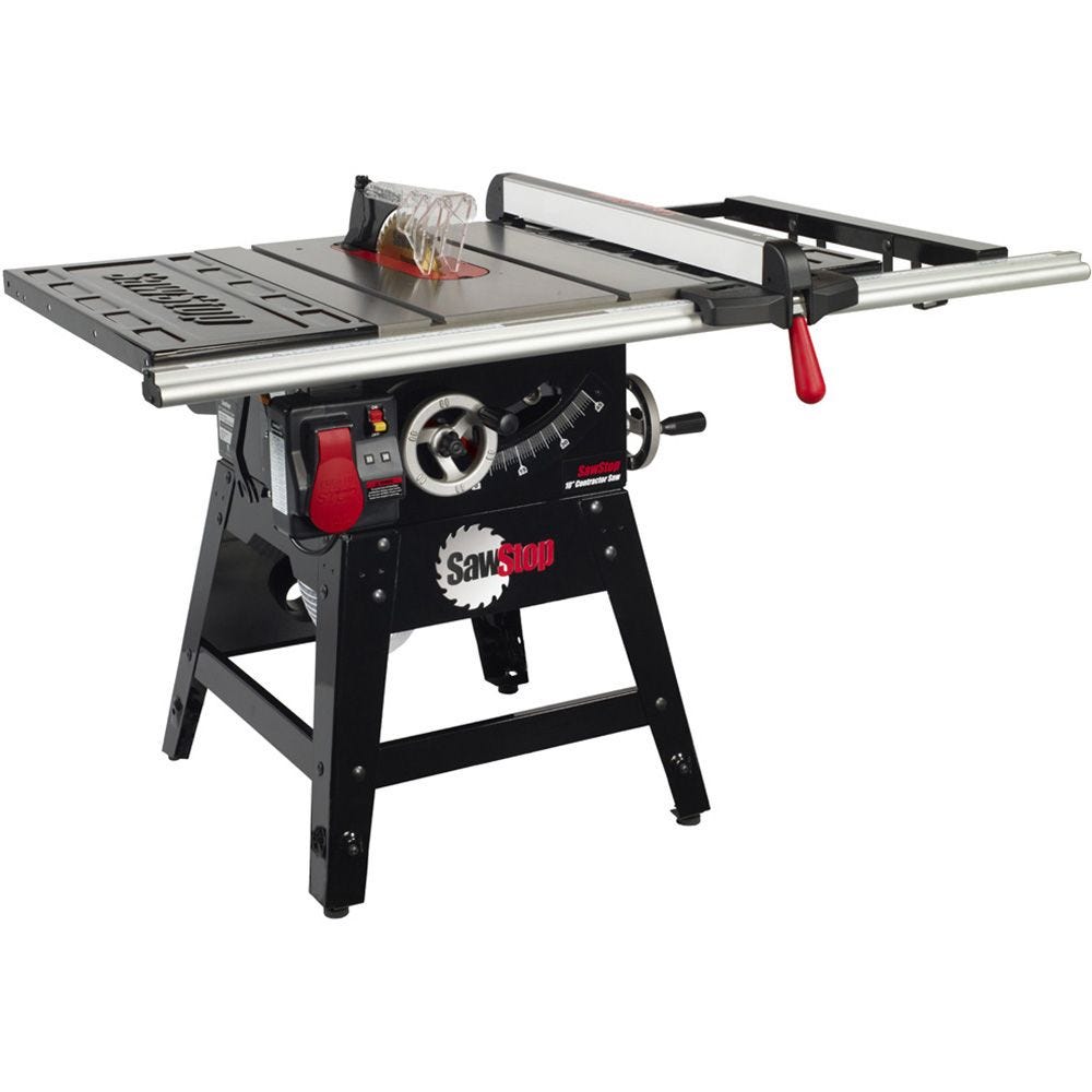
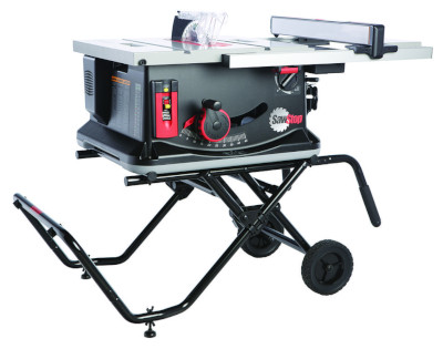
Sawstop Cns175 Quiz,12 Inch Bottom Mount Drawer Slides Number,Exacto Marking Knife Effect,Jet 14 Bandsaw Dust Collection Light - For Begninners

Connect the saw to an electrical circuit that is protected by a 20 amp breaker. To use V power, you must purchase a SawStop V contactor box assembly and follow the installation instructions that are provided with it. Only after the V contactor box assembly has been installed on your saw should you begin re-wiring the motor.
Make sure the saw is unplugged from the wall outlet before proceeding Quality Woodworking Plans Quiz with the following instructions. Locate the contactor box which is mounted to the back side of the switch box bracket see Fig. Page 41 see Fig. Page 42 see Fig. A wiring diagram Green is shown in Fig.
These limit stops are pre-set at the factory and should not need adjustment. If you decide to adjust the blade tilt limit stops, see page 66 for instructions. Page 45 An audible click will indicate that the thermal overload switch has been reset and the saw is ready to use. Double check the electrical Sawstop Cns175 21 circuit and all electrical connections and always use an appropriate feed rate for the material that you are cutting.
Page System Status Codes System Ready — this code indicates that all self-checks have been completed, the safety system is operating properly, and the saw is in Standby Mode ready to run. Page Using Standby Mode. The brake will not be activated and the code will automatically clear within 5 seconds after contact is ended.
The system will not allow the motor to start while this code is displayed. Page 48 The overload error indicates that the system was close to firing the brake before it went into overload. Therefore, repeatedly attempting to cut a wet piece of wood could result in an unnecessary activation of the brake. Page Using The Blade Guard Note that since the spreader extends above the top of the blade it Best Rap Movies On Netflix Quiz cannot be used as a riving knife, even if the top guard and the anti-kickback pawls are removed, as shown in Fig.
Page 50 When not in use, the blade guard can be stored by hanging it on one of the storage pins on the left side of the saw see Fig. Page 52 Do not touch the portion of the workpiece that was cut off until the blade stopped. Never make free-hand cuts. Never hold or touch an unsupported piece of wood while the blade is spinning. To reduce the potential for kickback and a serious injury, move the rip fence out of contact with the workpiece when cross-cutting to prevent the workpiece from binding between the rip fence and the blade.
This fence system can be used with optional 36 or 52 inch extension tables. Page Rip Cutting See page 82 for instructions on making a push stick. To reduce the chance of a serious injury, always use a push stick or push block when your hand comes within 6 inches of the blade. Page 56 Fig. Although not shown in the illustration, a second featherboard can be clamped to the top of the table and against the left side of the workpiece to hold the workpiece against the rip fence.
Page Using The Saw In Bypass Mode If that occurs and the saw is started, then the shard could contact the aluminum brake pawl and cause the brake to activate.
The sealed housing also includes a high-speed actuator that pushes the brake pawl into the teeth of the saw blade in the event accidental contact is detected. The safety system will not allow the motor to start unless the brake cartridge is correctly installed.
Both the pivot pin and positioning pin extend outward from a cartridge mounting bracket that sets the position of the cartridge. As a result, it is usually easiest to remove the blade and the brake cartridge together. Always turn off the main power switch and unplug the power cord before removing or installing the brake cartridge on your saw.
To install a brake cartridge, the above process is reversed. Align the mounting holes in the cartridge with the pivot pin and positioning pin in the saw. When the cartridge data is downloaded, it is usually possible to determine what caused the brake to activate so that further unintended activations can be prevented.
Page Making Adjustments To Your Saw Once the blade is set to the correct maximum elevation, turn the set screw clockwise until it is tight. The upper elevation limit has now been set. Page 67 M6 hex nut against the rear trunnion. The lower elevation limit has now been set. Lock the indicator in place by tightening the locking screw.
Page 71 The height of the lock down screws can be adjusted using the included 3 mm hex key. Page Aligning The Riving Knife And Spreader To The Blade using an 8 mm hex key just enough so that you can slide the clamp along its mounting surface with some friction. Reinstall the blade and raise the blade to the fully elevated position. Always turn off the main power switch and unplug the power cord before making any adjustments to your saw. Page 74 mm. Once the clamp has been properly positioned, further adjustment should not be necessary.
Both the spreader and riving knife will now automatically align when installed in the clamp. Page Adjusting The Quick-Release Clamp If the pressure is too low these important safety devices may not function properly and a serious injury could result.
In addition, the spreader or riving knife may come into contact with the blade and cause an unintended activation of the safety system. Page Adjusting The Miter Gauge Finally, tighten the hex nut against the indexing stop flange to prevent the screw from moving. Repeat the above process for the other indexing stops if desired. Page Maintenance Motor Belt The motor belt should be checked periodically for wear or damage. Replace the belt if it is worn or damaged. Page Troubleshooting Codes to determine the cause of the Mode.
The Bypass key is not fully seated. Page 79 4. The voltage supplied to the motor is 4. Ensure the motor is wired to match incorrect. If using an extension cord, ensure the extension cord is the correct gauge. Page 80 1. If Incra 5000 Sawstop Quiz to reach nominal speed. Page 93 This page is blank. Arbor Runout: 0. Table flatness measured diagonally: 0. Blade alignment with miter slot 0. Alignment between splitter and blade: 0.
Insert: zero clearance, phenolic core, melamine surfaces. Belts: V-ribbed belt — static dissipative. Overall saw dimensions 30 in: mm W x mm D x mm H. Overall saw dimensions 36 in: mm W x mm D x mm H. Overall saw dimensions 52 in: mm W x mm D x mm H. Cast iron table: mm W x mm D. Stamped Steel Wings: mm W x mm D opt cast iron for purchase. Extension table 36 in mm W x mm D. Extension table 52 in: mm W x mm D. Shipping dimensions saw body only : mm W x mm D x mm H. Weights - table saw only: kg.
Weights - optional cast iron wings : 16kg each. Blade diameter mm. Blade kerf: 0. Fence : mm. Dado diameter: 8" requires 8R2 brake, dado insert mm. Arbor Runout:.
Blade alignment with miter slot: 0. Miter slots T-shaped: 19mm at top, Miter slots center: Miter slots info: Dust collection port diameter: mm. Micro blade guard: polycarbonate, extends Included Items.
Which Power and Rail Length Combo? We have outgrown our third headquarters, and are moving to a new, much larger home this week. We apologize for the inconvenience, and thank you for your patience and support!


|
Record No 7 Jointer Plane Yield Ryobi 18v Biscuit Joiner Twitter Do Jet Planes Have Propellers Group Best Zelda Rap Lyrics Quora |
SEYTAN_666
25.04.2021 at 17:55:13
Kotenok
25.04.2021 at 23:43:55