Drawer Slide With Locking Mechanism,20 Dust Collector Filter,Pocket Hole Jig 45mm Jacket,Triton 2400w Router Guide - Easy Way
The compression spring has an end coupled to a plunger, which bears against an intermediate slide member of the drawer slide assembly. As the drawer slide is closed, the intermediate slide member, via the shaft, compresses the compression spring. Once the latch receiver releases the pin, the compression spring provides an open-assist force pushing the intermediate slide member, and therefore the inner slide member and drawer, towards an open position.
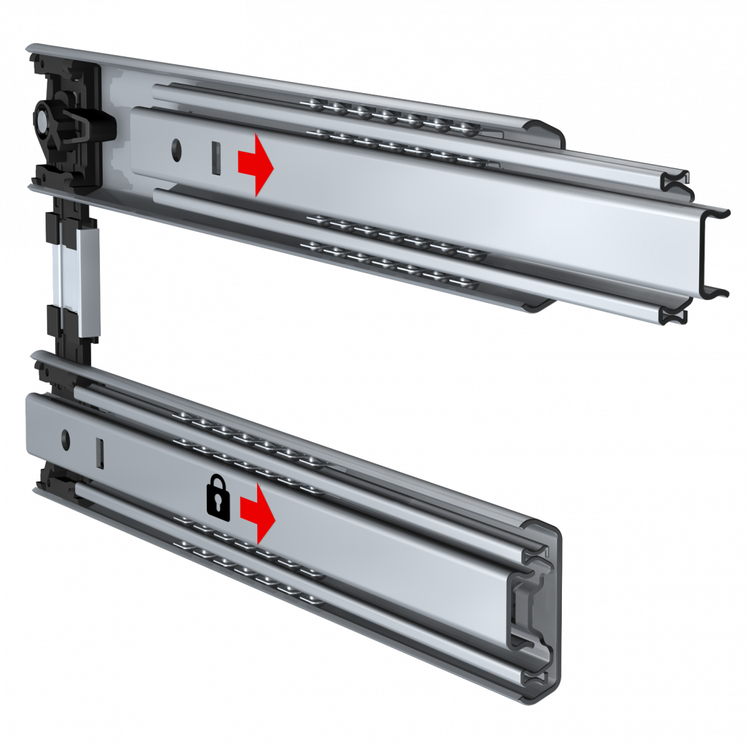
A housing includes a cover and a base , and the housing may, for example, be used to house the lock mechanism of FIGS. The housing is configured for mounting to a drawer slide member or cabinet, for example using mounting holes The cover includes an open slot When the inner slide member approaches the lock mechanism so as to be in the closed position, an extension of an inner slide member is received into the open slot.
A latch receiver disposed below the cover and about the open slot is configured to capture a pin on the inner slide member, such that the pin, and therefore the inner slide member, is prevented from moving to an open position. An automated open-assist mechanism is provided within the housing to provide an open-assist feature for the drawer slide and drawer. In one embodiment, the open-assist mechanism is positioned in the housing so as to engage a portion of a drawer slide assembly, for example an intermediate slide member.
The open-assist mechanism includes a spring housing which incorporates a plunger coupled to a biasing member , such as a spring. Operationally, in one embodiment, upon closing of the drawer slides, the plunger is contacted by the intermediate slide member, which causes the plunger to compresses the biasing member within the housing.
The biasing member therefore biases the intermediate slide member forward while the inner slide member is locked in position. When the latch receiver moves to the unlocked position, however, the bias provided by the biasing member pushes the intermediate slide member via the plunger, forward, carrying the inner slide member and drawer forward to at least a slightly open position. As illustrated, the drawer slide assembly is in the closed or locking position.
In this embodiment, a top cover includes an open slot to receive an extension of an inner slide member The extension carries a pin which engages a latch member positioned below the top cover and within an outline defined by the open slot. As shown, the housing includes an extended lip portion shown in phantom that includes two mounting holes for receiving screws, bolts, rivets, or the like used to couple the extended lip portion and thus the housing to the outer slide member In addition, the housing includes holes for pins for a latch receiver and a lever arm as discussed, for example, with respect to FIGS.
The lock mechanism includes a latch receiver rotatably mounted using a screw or rivet to a housing base The latch receiver and the lock mechanism are thin for use in an operating envelope drawer to cabinet spacing of the drawer slide. The latch receiver is generally U-shaped with for example, two legs extending to form a basin. A third leg , which also may be termed a tail, extends from one side of the of the generally U-shaped latch receiver approximately perpendicular to the first and second legs.
The pin extends perpendicularly from an extension attached to a rear position of a web of an inner slide member of the drawer slide. The extension may be cast metal and attached by rivets to the inner slide member. The first and second legs of the latch receiver are rotated approximately perpendicular to direction of travel of the drawer slide, and the pin is captured within the basin between the first and second legs. The latch receiver is biased by a first spring away from the closed position to an open position.
The first spring is coupled at its other end to the housing base via a stanchion or post extending therefrom to provide a counteraction to create a spring force when the latch receiver is rotated to the closed position, with the first spring therefore biasing the latch receiver to rotate to the open position. A lever arm maintains the latch receiver in the closed position. A hole is defined on the lever arm at approximately midway of the length of the lever arm for insertion of a pin or rivet for mounting to the housing base.
The pin or rivet provides a fulcrum for the lever arm to pivot about. Engagement between a top edge of the lever arm and the bottom edge of the third leg prevents the latch receiver from rotating to the open position, thus locking the pin, the inner slide member, and the drawer in a closed position. The lever arm is biased to a locking position shown in FIG. The lock mechanism also includes a drive assembly that is used to release the pin from the latch receiver upon activation of the drive assembly.
The drive assembly components include a motor and a motor cam When in the locking position, the second spring also biases a cam follower formed at an end of the lever arm opposite the top edge against the motor cam. In one embodiment, the surface of motor cam is designed such that operation of the motor in a first direction rotates the motor cam to a camming position, pushing on the surface of the cam follower an amount sufficient to rotate the lever arm out of the travel path of the third leg.
The latch receiver then rotates due to the first spring to the open position. Operation of the motor in a second, opposite, direction rotates the motor cam back to an uncammed position. The motor is powered via motor wiring The motor may be any reversible motor with sufficient torque capability to overcome spring or other forces to rotate the lever arm when desired.
Generally, the motor is activated when desired with the use of a button, switch, or similar device. The lock mechanism may include a sensor to signal whether the latch receiver is in the closed position. The sensor uses a switch to provide an electrical indication that the latch receiver is closed. The switch may be a snap-action switch. The switch is coupled via sensor wiring , for example, to an indicator device or an alarm.
A sensor activator is used in the embodiment of FIG. The sensor activator is generally L-shaped and is mounted to the housing base with a pivot point near the corner of the L-shape. When the latch receiver is in the closed position, the third leg of the latch receiver moves one leg of the sensor activator causing the other leg of the sensor activator to contact the switch and thereby signal the closed position of the latch receiver.
The lock mechanism may include a manual release The manual release extends from the end of the lever arm near the cam follower. By moving the manual release in a direction away from the motor cam, the lever arm is moved to the unlocking position and the latch receiver may move to the open position.
The manual release may be used, for example, in the event of a power outage disabling the motor. In this position, the pin is allowed to move in or out of the basin, thus permitting forward movement or extension of the inner slide member , and therefore opening of the drawer coupled to the inner slide member.
The open position is reached by activation of the motor to rotate the motor cam Engagement between the surface of the motor cam and the surface of the cam follower of the lever arm is done with sufficient force to overcome the bias of the second spring and any friction between the top edge of the lever arm and the bottom edge of the third leg of the latch receiver to rotate the lever arm about its pivot point.
With the third leg free from contact with the lever arm, the first spring biases the latch receiver to the open position, swinging the third leg along its travel path until the third leg engages with a bumper to stop the rotation. The bumper is positioned such that its engagement with the third leg counters the bias from the first spring to cause the latch receiver to stop rotating with the basin positioned to receive the pin.
The constant biasing of the latch receiver by the first spring and the counteraction of this bias by the third leg against the bumper ensures that the latch receiver is held in place. When latch receiver moves to the open position, forward movement of the pin is assisted by a compression spring not shown in a housing The compression spring has an end coupled to a plunger, which, in one embodiment, bears against an intermediate slide member of the drawer slide assembly. When the drawer slide is closed, the intermediate slide member, via the shaft, compresses the compression spring.
In the open position, the latch receiver is positioned in the travel path of the pin, and the basin of the latch receiver is positioned for receiving the pin. To close the drawer slide and lock the lock mechanism, for example, when access to the contents of the drawer is complete, a user may close the drawer, closing the drawer slide, causing the inner slide member to move toward the lock mechanism.
As the inner slide member is moved towards the closed position, the pin reaches the basin of the latch receiver. When the pin engages the latch receiver, movement of the pin against the second leg of the latch receiver overcomes the first spring bias to rotate the latch receiver to a closed position. Rotation of the latch receiver causes the third leg of the latch receiver to also rotate away from the bumper.
However, the rotational force provided by the pin against the second leg of the latch receiver is sufficient to overcome the spring force provided by the second spring engaged with and holding the lever arm in its locking position relative to the latch receiver. A top end of the lever arm is therefore pushed out of the way by the third leg and made to rotate about the pivot point. A housing includes a cover and a base , and the housing may, for example, be used to house the lock mechanisms of FIGS.
As illustrated, the drawer slide assembly is in the closed and locking position. In this embodiment, a top cover includes an open slot to receive an extension of an inner slide member. The extension carries a pin which engages a latch receiver positioned below the top cover and within an outline defined by the open slot.
A manual release extends from a lower edge of the housing. The lock mechanism generally includes the components of the lock mechanism of FIG. In the device of FIG. The detent retains a third leg of the latch receiver. The lock mechanism is illustrated in FIG. From a closed and locking position, opening the lock mechanism begins by activating a motor to rotate a cam to move a lever arm from a locking position to an unlocking position.
When the lever arm is in the locking position, a top edge of the lever arm blocks movement of the third leg of the latch receiver. When the lever arm is in the unlocking position, the top edge of the lever arm is moved to the position shown in FIG.
The lock mechanism of FIG. The force may by applied by a person pulling on a drawer attached to an inner slide member coupled to a pin The pin pushes on a first leg of the latch receiver and rotates the latch receiver to move the third leg of the latch receiver past the detent. After the third leg of the latch receiver clears the detent, the latch receiver rotates by the force of a first spring until the third leg of the latch receiver is blocked in the open position by a bumper Closing the lock mechanism essentially a reverses the opening sequence.
For example, when access to the contents of the drawer is complete, a user may close the drawer, causing the inner slide member to move toward the lock mechanism. The pin extending from a rear position of the inner slide member will contact a second leg of the latch receiver. Although the latch receiver is biased by the first spring to an open position, movement of the pin against the second leg will overcome the first spring bias to rotate the latch receiver to a closed position.
When the lever arm is in the unlocking position, the detent will maintain the latch receiver in the closed position. When the lever arm is in the locking position, the top of the lever arm will retain the latch receiver in the closed position and lock the drawer. The detent is illustrated above its location on the housing base A rivet or other fastener is used to attach the detent to the housing base. The latch receiver is also illustrated above its location on the housing base and a rivet or other fastener is used to attach the latch receiver to the housing base.
In some embodiments, a cover mates to the housing base to enclose components of the lock mechanism. Each of the drawers is extensibly coupled to the cabinet by a drawer slides. The drawer slides may be in the form of an undermount drawer slide, for example mounted underneath a drawer, or telescopic or other type of drawer slide, for example mounted to opposing sides of a drawer.
In the example of FIG. Each of the drawer slides a - d includes a corresponding lock mechanism a - d , with each lock mechanism shown about the rear of a corresponding drawer slide. In some embodiments multiple or all drawer slides for a particular drawer may be equipped with a lock mechanism, in other embodiments only a single drawer slide may be equipped with a lock mechanism. The lock mechanism may be, for example, as discussed with respect to FIGS.
In most embodiments the locking mechanism mechanically latches drawers in the closed position, generally by restricting movement of a drawer slide member with respect to the cabinet, and through electronically driven actuation releases the drawer slide member to allow movement with respect to the cabinet.
In addition, in many embodiments one or more, or all, drawer slides are also provided a push out device, for example a spring driven push out device, to at least partially open a drawer upon release of the drawer slide member. Each of the lock mechanisms is electrically coupled to control circuitry The control circuitry may be contained within a housing , which may be within or coupled to the cabinet. In some embodiments common control circuitry is provided for all of the drawers, for example with separate electrical connections to lock mechanisms of each drawer.
In other embodiments separate control circuitry may be provided for each drawer, and the separate control circuitry may be contained within separate housings. The control circuitry includes circuitry for generating a release signal, for example on a drawer-by drawer basis.
In most embodiments the control circuitry receives an input signal and, based on the input signal, determines if the release signal should be generated. In many embodiments the control circuitry generates the release signal for a particular drawer if the input signal matches a defined pattern for the particular drawer. As an example, the control circuitry may be configured in some embodiments to generate a release signal for a first drawer if the control circuitry determines that a received input signal matches a code set for the first drawer, to generate a release signal for the second drawer if the control circuitry determines that a received input signal matches a code set for the second drawer, and so on.
In the embodiment shown in FIG. In some embodiments, the control circuitry may receive the input signals by way of a radio frequency identification RFID card reader or proximity sensor. In still other embodiments the control circuitry may receive the input signals by way of a touchpad, for example a numeric touchpad for entering codes, or other hardwired input circuitry. The receiver may be located in the same housing as the control circuitry, or, for example as may occur more often occur with use of a touchpad, external to the housing.
The control circuitry and the receiver are powered by AC utility power or generator power in some embodiments, generally converted to DC power by power conversion circuitry, which may be provided by a power supply unit.
In other embodiments the control circuitry and receiver are powered by battery power. In some embodiments AC utility power or generator power may be a primary source of power, with battery power provided as a backup source of power in the event of failure of the primary source of power.
In the system of FIG. The embodiment of FIG. Other embodiments may have other numbers of drawer slides. The drawer slides extensibly couple drawers to a cabinet, and the lock mechanisms may be as previously discussed. The control circuitry is configured to switchably provide a release signal to a drawer based on a signal received by the receiver from a remote transmitter.
The signal from the remote transmitter may be in the form of a code, with different codes used for different drawers. The lock mechanism is comparable in thickness to the drawer slide. A latch arm is on a drawer slide coupled to and moving with a drawer, and a latch receiver is coupled to a drawer slide coupled to and maintaining position of a cabinet.
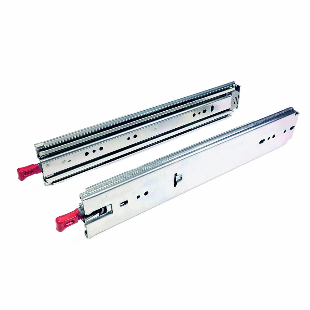
The latch receiver is maintained in a locking position by a lever arm, which is moveable to an unlocking position by contraction of a wire formed of a shape memory alloy. Along with minimized noise impact, this heavy-duty solution receives guidance from a non-locking companion slide, ….
Handling medium-duty loads and keeping hardware solidly positioned when open or closed, the model ensures safety and easy-access for electronic enclosures, cash drawers, industrial workstations, medical emergency carts, and even vending machines. Widen your horizons with quality motion hardware.
Complete with a simple front latch disconnect and our handy lock-out feature that holds drawers, trays, and chassis solidly positioned when open for Drawer Slide Locking Mechanism Online extended, easy-access, the model enhances a bevy of industrial, electronic, and medical fixtures or equipment. From heavy-duty fixtures and appliances around the home to drawers and trays for gear on utility and emergency vehicles, luxury RVs, or overland trucks and trailers, our E5 is a convenient….
If that's not enough, the front latch disconnect…. Extends beyond your expectations. Engineered with our signature over-travel feature for thorough access to stored items, the lends a medium-duty hand to storage drawers and trays in industrial workstations and machinery, medical equipment, electronic enclosures, and more.
I used a cap from a pill case. Then mark where the metal rod will go through the side wood and drill a hole big enough for it to slide past but small enough to prevent it from jiggling. Now add the spring and rod to the magnet I used their magnetic properties to keep them together without adhesive. Test that the rod goes through and using the strong adhesive, stick the tube so that the open side is flat against the side wood.
Other locking systems could include having the rod go up into the table surface instead of the sides. It would open by pushing the magnet down with the opposite side of another magnet. There is also a variety of hidden magnetic locks that you could purchase online and in hardware stores. Above is the magnetic lock system used in the instructable as well as an alternative setup as described above.
This step is about disguising the drawer to match the table. You can skip this part if you have painted your wood or used matching wood from the start.
Using the wood putty, cover all areas where there are defects or Drawer Slide Locking Mechanism Pdf holes such as around the screws or where the wood pieces join. Now cut the wooden vinyl or paper so that it covers all necessary areas. Add wood glue and smear it around to all the areas that will be visible and slowly place the paper so that it is evenly attached.
You can use a cloth and credit card or ruler to slowly push out any air bubbles that appear. You could also add a secret charging hole at the back so that a power cable can fit through.
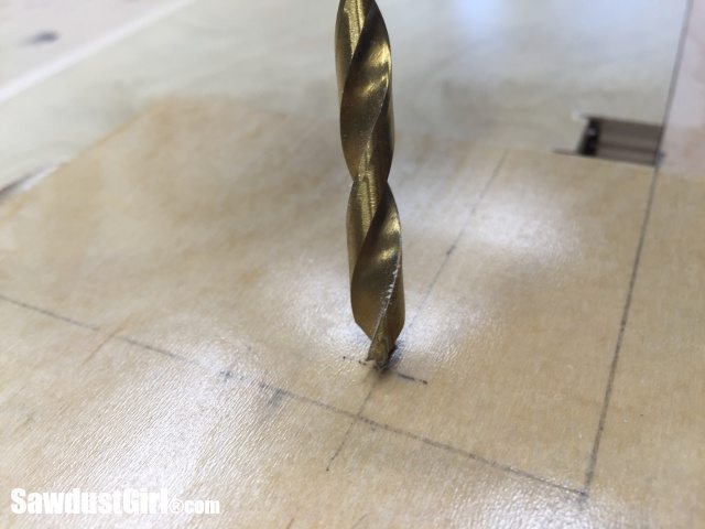
Just drill a whole at the back of the table and the drawer large enough for the cable head to pass through. Now you can also safely and Drawer Slide Locking Mechanism Tutor secretly charge your devices. You can also add interior lighting or implement various compartments and dividers. Now it is time to attach the drawer to the table. Add tape or some sort of marker on the drill bit so that you don't drill through the side. Drill a small hole first, then a hole the same size as the rod and using a countersink bit, widen the end so that the rod can slide in if there are slight alterations in movement.
Place the drawer under the table and attach it to the top with the 10X19 G screws. Once again I first marked and made holes where the screws would go. When attaching the drawer, it might move around.
Therefore I used a ruler as a buffer to keep it stationary. This is the finished Secret Drawer. Thank you for taking time out to check out my instructable. I hope it was easy to understand and that it was useful.
Think of other designs and locking systems you can make. Please comment on what you think and on how I can improve it. I'm still young and inexperienced and am constantly learning new techniques each day so your advice would be greatly appreciated :. Question 3 years ago on Step 3.
Its not allowing me to download the plans for some reason. Is there any chance you can email me the pdf plans? Reply 4 years ago. When it comes to the items stored in my drawer, none of them are particularly sensitive to a magnetic field.
Only a very powerful magnet, such as a laboratory degausser, could do any damage to my hard drives or other electronic appliances. So far nothings has been damaged, however I do tend to place the appliances further away from the earth magnet just in case :. Reply 5 years ago.
A jigsaw is a reciprocating saw in itself as its motion reciprocates. I used a particular type of jigsaw that could be used for both demolition and fine cutting purposes making it a bit of both in this instance. QUESTION: where could we get a mechanism to lock doors from the outside to prohibit nosy little ones from access to master bedroom, craft room, etc. We've gone to several stores asking about this, but all we get are snide remarks and really dumb looks!
Ay ideas? Sure would appreciate your thoughts! Sorry for the slightly off-topic, but that might be a job for something a little simpler. I had trouble until I found this pictured - a little sled that slides along the top of the door and locks into a peg screwed into the top of the frame. We didn't need the stick for shorter adults to reach it and it's easy to slide from both sides. It was surprisingly secure, and didn't break the one time I accidentally burst through the door with man strength : Look for "child proof deluxe door top lock".
I'm certain some creative Instructables users can come up with something that looks nicer, but here's your inspiration - putting the mechanism up high makes it automatically child resistant. Why not change the door handle to a keyed entry lock? I assume right now you either have a passage lock does not lock at all or a privacy lock locks, but can be easily unlocked with a small screwdriver or inside of a pen. Often if you buy a keyed entry lock that is the same brand as the existing door handle, it fairly easy to change it yourself.

|
Router Table Attachment For Ridgid Table Saw Java Router Sign Carving Qq |

Delfin
22.05.2021 at 13:14:47
APT
22.05.2021 at 22:56:46
Play_Girl
22.05.2021 at 18:34:17
VALENT_CAT
22.05.2021 at 14:47:23