Drawer Slide Locking Mechanism Vba,Kreg Mini Pocket Hole Jig Manual,14 Sand Oaks Laguna Niguel - How to DIY
As the user continues to slide the drawer closed, the pin is forced against a second leg of the generally U-shaped latch receiver, which is in the travel path of the pin. The force of the pin against the second leg overcomes the bias of first spring to rotate the latch receiver from the open or unlocking position to the closed or locking position shown in FIG.
Rotation of the latch receiver causes a third leg of the latch receiver to also rotate away from the bumper. As shown in FIG. Accordingly, the third leg of the latch receiver contacts or bumps the lever arm while rotating. However, the rotational force provided by the pin against the second leg of the latch receiver is sufficient to overcome the spring force provided by a second spring engaged with and holding the lever arm in its ready or locking position relative to the latch receiver.
A top end of the lever arm is therefore pushed out of the way by the third leg and made to rotate about the fulcrum, or pivot point. The rotation of a bottom end of the lever arm causes the second spring to be compressed. Engagement between the top edge of the lever arm and the bottom edge of the third leg prevents the latch receiver from rotating back to the open position, thus locking the pin, the inner slide member, and the drawer in a closed position.
Upon activation of the motor, for example, by the depression of a button, the throwing of a switch, after drive circuitry receives a coded signal and the like, the latch receiver is returned to its open position. Activation of the motor rotates a motor cam The engagement between the surface of the motor cam and the surface of a cam follower of the lever arm is done with sufficient force to overcome the bias of the second spring and any friction between the top edge of the lever arm and the bottom edge of the third leg to rotate the lever arm about its pivot point.
The rotation of the lever arm moves the top edge of the lever arm out of the travel path of the third leg of the latch receiver. With the third leg free from contact with the lever arm, the first spring biases the latch receiver to the unlocking position, swinging the third leg along its travel path until the third leg once again engages with a bumper to stop the rotation.
The pin, and therefore the inner slide member and drawer, are free to move to a forward extended position. Forward movement of the pin is assisted by a compression spring not shown in a housing The compression spring has an end coupled to a plunger, which bears against an intermediate slide member of the drawer slide assembly.
As the drawer slide is closed, the intermediate slide member, via the shaft, compresses the compression spring. Once the latch receiver releases the pin, the compression spring provides an open-assist force pushing the intermediate slide member, and therefore the inner slide member and drawer, towards an open position. A housing includes a cover and a base , and the housing may, for example, be used to house the lock mechanism of FIGS.
The housing is configured for mounting to a drawer slide member or cabinet, for example using mounting holes The cover includes an open slot When the inner slide member approaches the lock mechanism so as to be in the closed position, an extension of an inner slide member is received into the open slot.
A latch receiver disposed below the cover and about the open slot is configured to capture a pin on the inner slide member, such that the pin, and therefore the inner slide member, is prevented from moving to an open position. An automated open-assist mechanism is provided within the housing to provide an open-assist feature for the drawer slide and drawer. In one embodiment, the open-assist mechanism is positioned in the housing so as to engage a portion of a drawer slide assembly, for example an intermediate slide member.
The open-assist mechanism includes a spring housing which incorporates a plunger coupled to a biasing member , such as a spring. Operationally, in one embodiment, upon closing of the drawer slides, the plunger is contacted by the intermediate slide member, which causes the plunger to compresses the biasing member within the housing. The biasing member therefore biases the intermediate slide member forward while the inner slide member is locked in position.
When the latch receiver moves to the unlocked position, however, the bias provided by the biasing member pushes the intermediate slide member via the plunger, forward, carrying the inner slide member and drawer forward to at least a slightly open position.
As illustrated, the drawer slide assembly is in the closed or locking position. In this embodiment, a top cover includes an open slot to receive an extension of an inner slide member The extension carries a pin which engages a latch member positioned below the top cover and within an outline defined by the open slot. As shown, the housing includes an extended lip portion shown in phantom that includes two mounting holes for receiving screws, bolts, rivets, or the like used to couple the extended lip portion and thus the housing to the outer slide member In addition, the housing includes holes for pins for a latch receiver and a lever arm as discussed, for example, with respect to FIGS.
The lock mechanism includes a latch receiver rotatably mounted using a screw or rivet to a housing base The latch receiver and the lock mechanism are thin for use in an operating envelope drawer to cabinet spacing of the drawer slide. The latch receiver is generally U-shaped with for example, two legs extending to form a basin.
A third leg , which also may be termed a tail, extends from one side of the of the generally U-shaped latch receiver approximately perpendicular to the first and second legs. The pin extends perpendicularly from an extension attached to a rear position of a web of an inner slide member of the drawer slide. The extension may be cast metal and attached by rivets to the inner slide member.
The first and second legs of the latch receiver are rotated approximately perpendicular to direction of travel of the drawer slide, and the pin is captured within the basin between the first and second legs. The latch receiver is biased by a first spring away from the closed position to an open position.
The first spring is coupled at its other end to the housing base via a stanchion or post extending therefrom to provide a counteraction to create a spring force when the latch receiver is rotated to the closed position, with the first spring therefore biasing the latch receiver to rotate to the open position. A lever arm maintains the latch receiver in the closed position.
A hole is defined on the lever arm at approximately midway of the length of the lever arm for insertion of a pin or rivet for mounting to the housing base. The pin or rivet provides a fulcrum for the lever arm to pivot about.
Engagement between a top edge of the lever arm and the bottom edge of the third leg prevents the latch receiver from rotating to the open position, thus locking the pin, the inner slide member, and the drawer in a closed position.
The lever arm is biased to a locking position shown in FIG. The lock mechanism also includes a drive assembly that is used to release the pin from the latch receiver upon activation of the drive assembly. The drive assembly components include a motor and a motor cam When in the locking position, the second spring also biases a cam follower formed at an end of the lever arm opposite the top edge against the motor cam.
In one embodiment, the surface of motor cam is designed such that operation of the motor in a first direction rotates the motor cam to a camming position, pushing on the surface of the cam follower an amount sufficient to rotate the lever arm out of the travel path of the third leg. The latch receiver then rotates due to the first spring to the open position.
Operation of the motor in a second, opposite, direction rotates the motor cam back to an uncammed position. The motor is powered via motor wiring The motor may be any reversible motor with sufficient torque capability to overcome spring or other forces to rotate the lever arm when desired.
Generally, the motor is activated when desired with the use of a button, switch, or similar device. The lock mechanism may include a sensor to signal whether the latch receiver is in the closed position. The sensor uses a switch to provide an electrical indication that the latch receiver is closed.
The switch may be a snap-action switch. The switch is coupled via sensor wiring , for example, to an indicator device or an alarm. A sensor activator is used in the embodiment of FIG. The sensor activator is generally L-shaped and is mounted to the housing base with a pivot point near the corner of the L-shape.
When the latch receiver is in the closed position, the third leg of the latch receiver moves one leg of the sensor activator causing the other leg of the sensor activator to contact the switch and thereby signal the closed position of the latch receiver.
The lock mechanism may include a manual release The manual release extends from the end of the lever arm near the cam follower. By moving the manual release in a direction away from the motor cam, the lever arm is moved to the unlocking position and the latch receiver may move to the open position. The manual release may be used, for example, in the event of a power outage disabling the motor.
In this position, the pin is allowed to move in or out of the basin, thus permitting forward movement or extension of the inner slide member , and therefore opening of the drawer coupled to the inner slide member. The open position is reached by activation of the motor to rotate the motor cam Engagement between the surface of the motor cam and the surface of the cam follower of the lever arm is done with sufficient force to overcome the bias of the second spring and any friction between the top edge of the lever arm and the bottom edge of the third leg of the latch receiver to rotate the lever arm about its pivot point.
With the third leg free from contact with the lever arm, the first spring biases the latch receiver to the open position, swinging the third leg along its travel path until the third leg engages with a bumper to stop the rotation. The bumper is positioned such that its engagement with the third leg counters the bias from the first spring to cause the latch receiver to stop rotating with the basin positioned to receive the pin.
The constant biasing of the latch receiver by the first spring and the counteraction of this bias by the third leg against the bumper ensures that the latch receiver is held in place. When latch receiver moves to the open position, forward movement of the pin is assisted by a compression spring not shown in a housing The compression spring has an end coupled to a plunger, which, in one embodiment, bears against an intermediate slide member of the drawer slide assembly.
When the drawer slide is closed, the intermediate slide member, via the shaft, compresses the compression spring. In the open position, the latch receiver is positioned in the travel path of the pin, and the basin of the latch receiver is positioned for receiving the pin.
To close the drawer slide and lock the lock mechanism, for example, when access to the contents of the drawer is complete, a user may close the drawer, closing the drawer slide, causing the inner slide member to move toward the lock mechanism.
As the inner slide member is moved towards the closed position, the pin reaches the basin of the latch receiver. When the pin engages the latch receiver, movement of the pin against the second leg of the latch receiver overcomes the first spring bias to rotate the latch receiver to a closed position. Rotation of the latch receiver causes the third leg of the latch receiver to also rotate away from the bumper.
However, the rotational force provided by the pin against the second leg of the latch receiver is sufficient to overcome the spring force provided by the second spring engaged with and holding the lever arm in its locking position relative to the latch receiver.
A top end of the lever arm is therefore pushed out of the way by the third leg and made to rotate about the pivot point. A housing includes a cover and a base , and the housing may, for example, be used to house the lock mechanisms of FIGS. As illustrated, the drawer slide assembly is in the closed and locking position. In this embodiment, a top cover includes an open slot to receive an extension of an inner slide member.
The extension carries a pin which engages a latch receiver positioned below the top cover and within an outline defined by the open slot. A manual release extends from a lower edge of the housing. The lock mechanism generally includes the components of the lock mechanism of FIG. In the device of FIG. The detent retains a third leg of the latch receiver. The lock mechanism is illustrated in FIG.
From a closed and locking position, opening the lock mechanism begins by activating a motor to rotate a cam to move a lever arm from a locking position to an unlocking position. When the lever arm is in the locking position, a top edge of the lever arm blocks movement of the third leg of the latch receiver.
When the lever arm is in the unlocking position, the top edge of the lever arm is moved to the position shown in FIG. The lock mechanism of FIG. The force may by applied by a person pulling on a drawer attached to an inner slide member coupled to a pin The pin pushes on a first leg of the latch receiver and rotates the latch receiver to move the third leg of the latch receiver past the detent.
After the third leg of the latch receiver clears the detent, the latch receiver rotates by the force of a first spring until the third leg of the latch receiver is blocked in the open position by a bumper Closing the lock mechanism essentially a reverses the opening sequence. For example, when access to the contents of the drawer is complete, a user may close the drawer, causing the inner slide member to move toward the lock mechanism.
The pin extending from a rear position of the inner slide member will contact a second leg of the latch receiver. Although the latch receiver is biased by the first spring to an open position, movement of the pin against the second leg will overcome the first spring bias to rotate the latch receiver to a closed position. When the lever arm is in the unlocking position, the detent will maintain the latch receiver in the closed position.
When the lever arm is in the locking position, the top of the lever arm will retain the latch receiver in the closed position and lock the drawer. The detent is illustrated above its location on the housing base A rivet or other fastener is used to attach the detent to the housing base. The latch receiver is also illustrated above its location on the housing base and a rivet or other fastener is used to attach the latch receiver to the housing base.
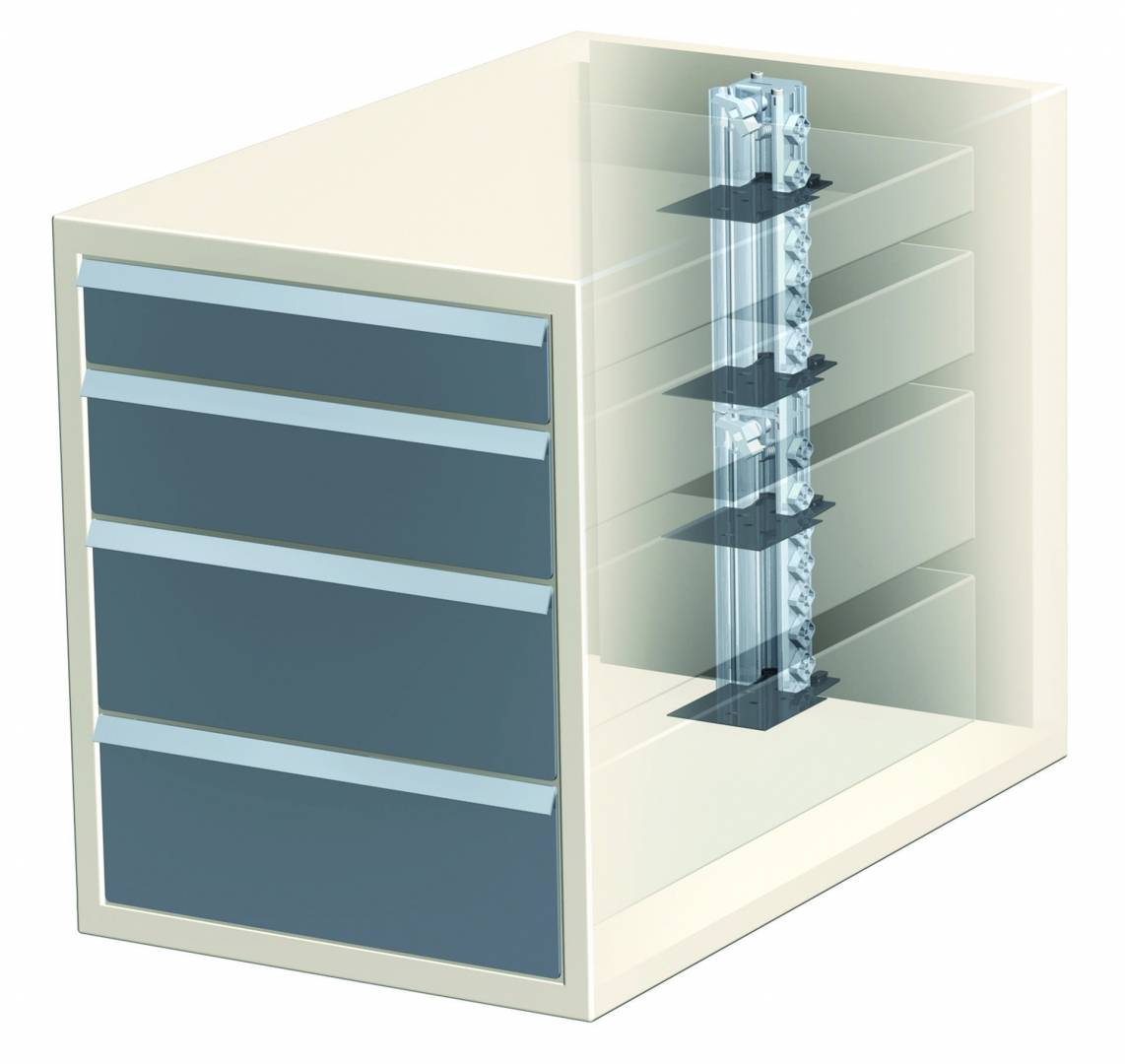
In some embodiments, a cover mates to the housing base to enclose components of the lock mechanism. Each of the drawers is extensibly coupled to the cabinet by a drawer slides.
The drawer slides may be in the form of an undermount drawer slide, for example mounted underneath a drawer, or telescopic or other type of drawer slide, for example mounted to opposing sides of a drawer. In the example of FIG. Each of the drawer slides a - d includes a corresponding lock mechanism a - d , with each lock mechanism shown about the rear of a corresponding drawer slide.
In some embodiments multiple or all drawer slides for a particular drawer may be equipped with a lock mechanism, in other embodiments only a single drawer slide may be equipped with a lock mechanism. The lock mechanism may be, for example, as discussed with respect to FIGS. In most embodiments the locking mechanism mechanically latches drawers in the closed position, generally by restricting movement of a drawer slide member with respect to the cabinet, and through electronically driven actuation releases the drawer slide member to allow movement with respect to the cabinet.
In addition, in many embodiments one or more, or all, drawer slides are also provided a push out device, for example a spring driven push out device, to at least partially open a drawer upon release of the drawer slide member. Each of the lock mechanisms is electrically coupled to control circuitry The Drawer Slide Locking Mechanism Online control circuitry may be contained within a housing , which may be within or coupled to the cabinet.
In some embodiments common control circuitry is provided for all of the drawers, for example with separate electrical connections to lock mechanisms of each drawer. In other embodiments separate control circuitry may be provided for each drawer, and the separate control circuitry may be contained within separate housings.
The control circuitry includes circuitry for generating a release signal, for example on a drawer-by drawer basis. In most embodiments the control circuitry receives an input signal and, based on the input signal, determines if the release signal should be generated.
In many embodiments the control circuitry generates the release signal for a particular drawer if the input signal matches a defined pattern for the particular drawer. As an example, the control circuitry may be configured in some embodiments to generate a release signal for a first drawer if the control circuitry determines that a received input signal matches a code set for the first drawer, to generate a release signal for the second drawer if the control circuitry determines that a received input signal matches a code set for the second drawer, and so on.
In the embodiment shown in FIG. In some embodiments, the control circuitry may receive the input signals by way of a radio frequency identification RFID card reader or proximity sensor. In still other embodiments the control circuitry may receive the input signals by way of a touchpad, for example a numeric touchpad for entering codes, or other hardwired input circuitry.
The receiver may be located in the same housing as the control circuitry, or, for example as may occur more often occur with use of a touchpad, external to the housing. The control circuitry and the receiver are powered by AC utility power or generator power in some embodiments, generally converted to DC power by power conversion circuitry, which may be provided by a power supply unit.
In other embodiments the control circuitry and receiver are powered by battery power. In some embodiments AC utility power or generator power may be a primary source of power, with battery power provided as a backup source of power in the event of failure of the primary source of power. In the system of FIG.
The embodiment of FIG. Other embodiments may have other numbers of drawer slides. The drawer slides extensibly couple drawers to a cabinet, and the lock mechanisms may be as previously discussed.
The control circuitry is configured to switchably provide a release signal to a drawer based on a signal received by the receiver from a remote transmitter.
The signal from the remote transmitter may be in the form of a code, with different codes used for different drawers. The lock mechanism is comparable in thickness to the drawer slide. A latch arm is on a drawer slide coupled to and moving with a drawer, and a latch receiver is coupled to a drawer slide coupled to and maintaining position of a cabinet.
The latch receiver is maintained in a locking position by a lever arm, which is moveable to an unlocking position by contraction of a wire formed of a shape memory alloy.
Contraction of the wire may be provided, for example, by passing a current through the wire. In some embodiments the latch receiver is maintained in the locking position by a top of the lever arm. In some embodiments the latch receiver is biased towards an open or unlocked position by a spring, and movement of the lever arm to the unlocking position, for example by contraction of the wire, releases the latch receiver to the unlocking position.
In some embodiments contraction of the wire is momentary, and the lever arm is biased to the locking position by a spring. In some embodiments the latch arm moves the latch receiver to the locking position when the drawer is closed.
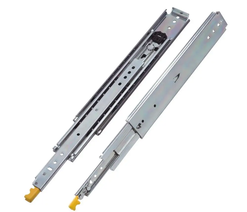
The three drawer slide members, which are coupled by way of ball bearings in many embodiments, are arranged with the intermediate member nested within the outer member, and the inner member in turn nested within the intermediate member. When mounted to a cabinet and a drawer, with the slide is in the closed position the intermediate and inner slide members are substantially within the volume of the outer slide member.
As shown, the pin extends from the web of the inner member and towards the web of the intermediate member. As the inner member approaches the closed position, the pin is received by a latch receiver , for example coupled to the outer slide member.
For the latch receiver of FIG. With the pin received by the latch receiver, the pin, and therefore the inner slide member is prevented from moving to an open position. The pin may be welded or otherwise attached to the web of the inner member, for example as by riveting with the pin being a rivet.
In other embodiments the pin may be formed of the material of the inner slide member, and may for example be in the form of a bayonet or other form punched or pressed from the material of the inner slide member.
Two legs extend from the body, a forward leg and a rear leg , with the two legs forming a basin for receiving the pin.
A tail extends from one side of the of the somewhat U-shaped latch receiver. In the open or unlocked position the opening of the basin faces towards a front of the cabinet, releasing the pin and allowing forward movement or extension of the inner slide member, and therefore opening of a drawer coupled to the inner slide member.
In the closed or locked position the opening of the basin is approximately perpendicular to direction of travel of the drawer slides. With the pin in the basin, therefore, the forward leg of the somewhat U-shaped latch receiver prevents forward movement of the pin, and therefore the drawer slide.
The latch receiver is biased to the open or unlocked position by a spring Counteracting the spring force, as shown in FIG. A top of the lever arm prevents rotation of the latch receiver to the open position, through contact with the tail of the latch receiver as shown in FIG. Rotation of the lever arm about its fulcrum allows the tail of the latch receiver to clear the top of the lever arm, allowing the spring of the latch receiver to rotate the latch receiver to the open or unlocked position.
The lever arm is biased to the locking position, with the top of the lever arm in the travel path of the tail of the latch receiver, by a spring The lever arm is rotated to the open position, with the top of the lever arm away from the tail of the receiver, by a wire The wire, as shown in FIG. Activation of the wire overcomes the spring force provided by the spring of the lever arm, and rotates the lever arm such that the tail of the latch receiver clears the top of the lever arm.
The wire is formed of a shape memory alloy. Shape memory alloys generally change shape upon heating and cooling, and are marketed, for example, by Dynalloy.
In most instances the shape memory alloy contracts upon heating, often provided by resistive heating upon passing a current through the wire, and the shape memory alloy expands upon subsequent cooling, which may be provided by merely removing the applied current and allowing ambient surrounding air to cool the alloy.
A shape memory alloy in the form of a wire is often beneficial, the wire has a relatively large surface area for its length, allowing for reduced time in cooling and consequent expansion of the wire.
Activation of the wire in FIG. The current in FIG. Placing the wire closer to the fulcrum of the lever arm allows for increased distance of movement of the top of the lever arm for a given contraction of the wire. In some embodiments power to provide the current is provided by a battery, with drive circuitry controlling application of the current. The battery may be, for example, a 1.
The drive circuitry may include circuitry such as voltage or current regulation circuitry and circuitry to determine when to apply power to the wire, or may be accompanied or coupled to such circuitry. In other embodiments power may be supplied by or through power outlets commonly found in residential or commercial settings, with the power supplied by a utility or back-up generator or the like.
A transformer may be used to convert AC supplied power to DC, particularly for use with the drive circuitry, although in some embodiments AC power may be supplied to the wire.
Two wires are provide in the embodiment of FIG. A first of the two wires may be used in normal operation. A second of the two wires may be used as a backup, for example in the event the first wire becomes damaged.
Moreover, the second wire may be provided an alternative energy source, for example a battery, and possibly alternative operating circuitry, for example in the event of a power failure of a primary energy source or damage to primary operating circuitry.
The use of the second wire as a back-up, and in some embodiments alternative drive circuitry, is beneficial in that operation of the locking mechanism may continue to be provided, at least temporarily, in the event of component or power failure, without, for example, requiring service by a technician to restore operation of the device.
In some embodiments drive circuitry for the wire is provided by circuitry activated by entry of a password or identification number by way of a keypad, by a signal, preferably encoded, from a wireless transmitter, or by some other way of receipt of a signal, preferably coded, indicating authorized opening of the drawer is requested.
Upon or after receiving the coded signal, the drive circuit passes current through the wire, with the current for example passing to ground through the lever arm or by way of a return wire. The wire contracts due to resistive heating, and pulls the lever arm out of the travel path of the tail of the latch receiver. The spring of the latch receiver biases the latch receiver to the unlocking position, and the pin, and therefore the inner slide member and drawer, are free to move to a forward extended position.
A further spring may be provided to provide an automatic opening feature for the drawer slide and drawer. Featuring a variety of finishes and outlet configurations for any type of project. Organize, charge and power everyday devices, while decluttering countertops.
Most popular and flexible solution. Connect up to 8 devices. Perfect for any drawer type. Connect up to 4 devices. Perfect for installations requiring 20 amps or commercial applications. Overnight, 2nd day and economy shipping available. We make returns easy with no restocking fee. Orders placed by noon are shipped the same day.
He said install was simple and was engineered to perfectly fit the cabinet. It works great and looking to buy another for my husband's home office. High quality product and worth the price.


|
Drill Master Pocket Hole Jig Video Mp3 Best Routers For Woodworking 2019 Qual Husky Gravity Feed Hvlp Spray Gun Review Design |

eminem4ik
25.06.2021 at 14:57:22
KISSKA325
25.06.2021 at 21:28:50