Drawer Lock Mechanism 01,Gel Stain Application Techniques Zone,Make A Birdhouse Out Of Wood Industries,Under Counter Drawer Freezer Llc - Good Point
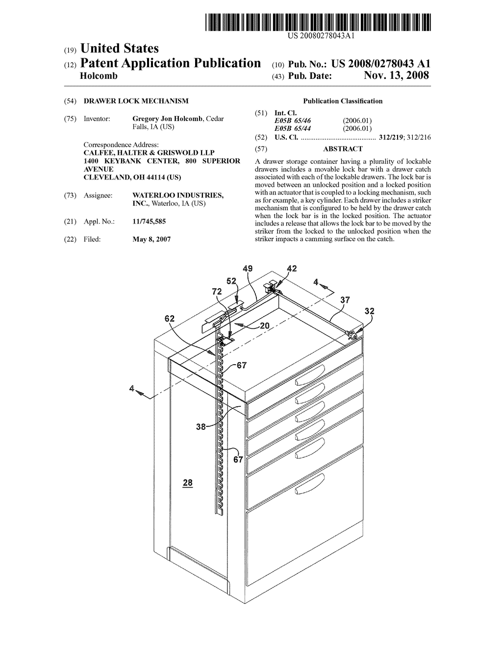
A generally L- shaped metal catch-plate or catch-plate means 3] is spot welded to the rear I6 of each drawer Ild. Each catch-plate 31 is formed with a generally V-shaped. The two channels diverge upwardly front a junction An angle plate 36 formed integrally with the catch-plate 31 extends rearwardly therefrom. The rearward channel 34 is bounded by a first hearing edge 37 constituting a lower marginal edge, and a second bearing edge 38 constituting an upper marginal edge.
The upper edge of the angle plate 36 is a third bearing edge 39 pitched generally rearwardly and downwardly of the rearward opening of the slot An important element of the anti-tilt lock mechanism is a metal lock rod 40 carried by the rear wall I4 of the cabinet frame.
A vertically spaced series of collars 4I affixed to the rear wall l4 encircles the lock rod 4" and constitutes guides preventing lateral movement of the lock rod 40 when it is shifted vertically upwardly and downwardly.
At vertically spaced positions along the lock rod 40 correlated with the catch-plates 3 affixed to the drawers. Pins 45 inserted through and extending laterally outwardly from each lock-plate 42 are sized and positioned to enter the slots 32 formed in the catch-plates 31 to bear upon the three bearing edges As shown in FIGS.
The detent includes a spring 5] affixed to a collar 4] and resiliently urging a lug 52 carried by the spring 5] into contact with the lock rod The lock rod 40 is formed with a socket or recess 53 adapted to receive and to frictionally secure the lug 52 when the lock rod 40 is raised to bring the socket 53 into mating correspondence with the Drawer Locking Mechanism lug S2.
The mode of operation of the anti-tilt lock mecha nism of the invention is shown in FIGS. When all four drawers are closed FIG. When a drawer Ilu is pulled outwardly FIG.
Elevation ofthis pin 45 raises the attached lock rod The remaining drawers llh, Ilt'. III, are thereby prevented from moving outwardly. The lock rod 40 is retained in its elevated. When the single open drawer I In is closed. The force applied by the catchplate 3] of the first drawer Ila is sufficient to overcome the frictional force of the lug 52 and socket S3 detaining the lock rod 4" in an elevated position.
After the lock rod 40 is lowered. Experience with other anti-tilt mechanisms in filing cabinets has shown that lock rods or bars will occasionally inadvertently slip downwardly from the position corresponding to FIG.
This problem can be caused by an imperfect mating fit between the lag and socket in the detent holding the rod or bar in place. When this problem occurs in conventional filing cabinets, corrections can he made only through the time-consuming cx pedient of disassembling the entire cabinet to restore the lock bar to its proper position The above-described problem can be corrected with relatively little effort in the anti-tilt mechanism of the present invention by operation of a fail-safe means in the form of an angle catch 36 formed integrally with the catch-plate 3.
If the lock rod 40 should inadvertently shift downwardly when one of the drawers is in a forward, open position. When the open drawer is closed. As the lock rod 40 is raised, each of the pins is restored to its respective slot The linkage includes a short link 42 that is rigidly connected to a key cylinder rod 37 such that rotation of the key cylinder is transmitted via the rod to the short link.
As can be seen best in FIGS. A spring 96 urges the short link 43 into proper alignment with the bracket 46 and actuator The link 49 is pressed into a distal end of the short link and is retained by a washer 45 that allows the link 49 to rotate within the short link In this manner, the linkage 42 allows the link 49 to move the actuator side to side in response to rotation of the key cylinder Movement of the key cylinder to lock the chest causes corresponding movement of the actuator 52 to the right and the guide pin 63 slides down the slanted camming slot portion 58 and into the lower horizontal slot portion 59 to rest in the position shown in FIG.
The vertical relief slot portion 53 is positioned above the guide pin so that there is clearance for the lock pin to move if the lock bar is lifted by the catch 67 impacting the striker plate 72 FIG. Movement of the key cylinder to unlock the chest causes corresponding movement of the actuator 52 to the left and the guide pin 63 slides up the slanted camming slot portion 58 and into the upper horizontal slot portion When the lock bar 62 is in this position, the catch 67 is positioned away from the opening 74 in the striker plate 72 and the drawer can be opened freely.
The key cylinder 32 FIG. The guide pin 63 rests in the lower horizontal slot portion 59 below the vertical relief slot portion In FIG. The lock bar is thus lifted by the striker plate 72 and the guide pin 63 moves up into the vertical relief slot portion Referring to FIG. Once the drawer has traveled to the closed position, the catch 67 falls into the opening 74 as shown in FIG. The drawer 32 is now locked in position. While various aspects of the invention are described and illustrated herein as embodied in combination in the exemplary embodiments, these various aspects may be realized in many alternative embodiments not shown, either individually or in various combinations and sub-combinations thereof.
Unless expressly excluded herein all such combinations and sub-combinations are intended to be within the scope of the present invention. Still further, while various alternative embodiments as to the various aspects and features of the invention, such as alternative materials, structures, configurations, methods, devices, and so on may be described herein, such descriptions are not intended to be a complete or exhaustive list of available alternative embodiments, whether presently known or later developed.
Those skilled in the art may readily adapt one or more of the aspects, concepts or features of the invention into additional embodiments within the scope of the present invention even if such embodiments are not expressly disclosed herein.
Additionally, even though some features, concepts or aspects of the invention may be described herein as being a preferred arrangement or method, such description is not intended to suggest that such feature is required or necessary unless expressly so stated. Still further, exemplary or representative values and ranges may be included to assist in understanding the present invention however; such values and ranges are not to be construed in a limiting sense and are intended to be critical values or ranges only if so expressly stated.
A drawer lock for use with a storage container having a top wall, a bottom wall, a pair of spaced side walls and a rear wall that define a drawer cavity in which one or more drawers are housed, the drawers being moveable between an open and a closed position, the drawer lock comprising: a striker disposed on a rear portion of each drawer, the striker including a retention feature;. The drawer lock of claim 1 wherein the vertical relief slot allows the lock bar to be moved to the unlocked position from the locked position by the striker.
The drawer lock of claim 1 comprising a vertical lock bar channel configured to be mounted to the rear wall. The drawer lock of claim 3 wherein the lock bar includes one or more friction reducers that define one or more surfaces upon which the lock bar slides within the lock bar channel. The drawer lock of claim 4 wherein the friction reducers comprise a plastic insert that is fitted into a corresponding notch on a side edge of the lock bar. The drawer lock of claim 5 wherein the plastic insert is made of nylon.
The drawer lock of claim 1 wherein the catch comprises a generally L-shaped finger that includes a first leg that projects orthogonally from the rear wall of the storage container and a second leg that projects orthogonally from the first leg toward the bottom of the storage container. The drawer lock of claim 7 wherein the striker comprises a plate and wherein the retention mechanism is an opening through the plate sized to receive the second leg of the L-shaped finger.
The drawer lock of claim 7 wherein the camming surface is a taper on a face of the second leg of the L-shaped finger that confronts the striker when the drawer is closed. The drawer lock of claim 7 wherein the striker includes an angled end portion at an end of the plate that contacts the second leg when the drawer is closed, wherein Drawer Slide With Locking Mechanism the angle end portion is bent toward the bottom of the storage container to urge the lock bar up to the unlocked position when the striker plate contacts the second leg of the L-shaped finger.
The drawer lock of claim 1 , wherein the container lock mechanism includes a key cylinder, a first link that is fixedly coupled to the key cylinder for rotation therewith, and a second link pivotally connected to the first link and connected to the actuator, such that keyed rotation of the key cylinder horizontally slides the actuator between the locked and unlocked positions.
USB2 en. EPA4 en. CNB en. CAC en. EPA4 en. CNB en. CAC en. MXA en. WOA1 en. USB1 en. USDS1 en. USA en. DEU en. FRA5 en. ATB en. ITB en. JPSB2 en. CAA en. ATT en. CAA1 en. USA1 en. CNA en. EPA1 en.

|
Woodworking Tool Sets For Sale Jointer Plane Blade Camber Order |

JAGUAR
21.06.2021 at 20:30:10
barawka
21.06.2021 at 21:54:27
KETR
21.06.2021 at 11:41:10