Slide Out Drawer Mechanism Codes,Etap Yachts,Jet Planes Fly In Which Layer Of Atmosphere Guide,Carving Bits For Router Ii - You Shoud Know

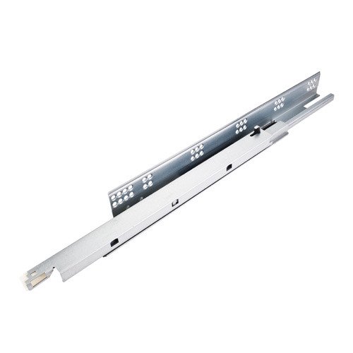
As illustrated in FIG. Thus, for example, adjacent members can be slid back and forth in the longitudinal direction relative to each other to perform operations such as opening and closing the drawer to which the drawer slide is attached. By positioning the adjustable detent mechanism at this location, the mechanism can be easily operated, for example, by slightly opening the drawer after the slide is installed.
By operating the detent mechanism, it is possible to adjust the detent mechanism to adjust the detent force provided by the mechanism when the closed drawer is opened. However, in one variant, the detent mechanism is positioned behind the slide. In terms of direction, the terms front and rear refer to locations on the slide near the front of the drawer and near the rear of the drawer, respectively.
I have. Preferably, the detent mechanism of the present invention is formed of molded plastic. This closed strip has a progressively sloped surface 19 that extends from the center point of the length of the oval body towards the top 27 of the head.
Opposing surface 21 extends away from gradient surface 19 on the opposite side of the top of the head. By forming the arm and the main body in this way, the assembly of the detent mechanism is considerably facilitated.
However, once the detent mechanism is ready to be placed in the drawer slide, the bridge is broken. In this way, the cylindrical head 34 at one end of the arm 24 can be placed in the socket 32 formed by the body and inside the closed strip.
On the opposite side of arm 24 is a shaped surface in which teeth or jagged portions 36 are formed. A tapered surface 48 extends beyond the teeth 36 in the opposite direction of the cylindrical head This tapered surface, its extension at the tip of the tooth and its location along one side of the arm can be seen in FIG.
A slot 40 dashed line in the side of the arm is also shown in FIG. This slot is suitable for accommodating a small screwdriver blade or the like to further facilitate the rotation of the arm once the cylindrical head is placed in the socket of the main body.
In one embodiment, a cut portion 50 shown in FIG. The cut portion or flank 50 of the intermediate slide member provides sufficient space for the inner slide member to be nested within the intermediate slide member without interfering with the travel of the adjustable detent mechanism.
However, in another embodiment, the longitudinal length of the intermediate slide member is such that the cut portion is not required because the portion of the intermediate slide that is to be cut is simply not there.
Therefore, the detent mechanism is suitable for contacting with a member extending from the outer slide member toward the intermediate slide member, and the intermediate slide member is configured such that the detent can be contacted with one extending from the outer slide member.
As illustrated, the tab is created by providing a cut or notch in the leading edge of the outer slide member 14 and forming a tab extending from the web of the slide member 14 toward the intermediate slide member It is a part of the molded member Thus, as can be seen in FIGS.
The tab engages surface 19 as the drawer is closed, and engages surface 21 when the drawer is in the closed position and when the drawer is initially forced to overcome detent or retention forces. Furthermore, it extends into the passage of the detent mechanism. As the tab comes into contact with the surface 21 or the surface 19, the strip forming the detent mechanism is compressed, otherwise it deforms or deflects the portion of the strip specifically formed by the head.
However, the arm resists compression of the strip. Since the position of the arm can be adjusted within the belt-like member, the ease of compression of the belt-like member can also be adjusted.
When fully closed, the flexible finger 22 encounters an end stop flange 28, providing cushioning for the inner slide member when the drawer slide is closed, and completely within the drawer slide itself. Reduce or eliminate noise on the inner slide member that will stop.
When the slide is fully closed, a sloped surface 21 opposite the slope 19 along the detent head is supported against the inner surface of the stopper member The combination of the flexible fingers supported on the end stop flange 28 and the surface 21 supported on the molded stop end member creates a locking effect to hold the drawer securely closed. When the drawer is opened, the position of the adjustable detent mechanism and adjustable arm 24 determines the amount of force required to pull the drawer slide out and open the drawer.
Depending on the field of use, the drawer slide may be used in a tool box or in a cabinet or desk. When used in a tool box, a larger detent or retention force is desirable. A lower detent or retention force is desirable when utilized in a drawer or cabinet. The fulcrum is directed toward the head by adjusting the flexible arm using a screwdriver inserted in the slot 40 of the adjustable arm and twisting the toothed edge of the adjustable arm toward the head The fulcrum arm is shortened to increase the detent or retention force.
Conversely, if the toothed surface of adjustable arm 24 is moved in the opposite direction toward flexible finger 22, the fulcrum arm is extended and the amount of detent or holding force created by the adjustment mechanism is reduced.
Is done. One end of the arm, ie the end with the cylindrical head, is held securely in the socket. The tooth at the other end is selectively engaged with one of the teeth 38 provided on the inner surface of the envelope adjacent the top surface of the adjustable detent mechanism.
The use of teeth on the inner surface of the envelope is advantageous in that the position of the arm can be adjusted in discrete increments, providing a quantified step with adjustment of the detent mechanism. The detent force is determined by positioning an adjustable arm for a specific tooth within the inner surface of the envelope. When the engaging portion is closer to the flexible finger 22, the fulcrum arm is extended and the detent force is reduced.
If the arm is engaged with teeth closer to the detent mechanism head 20, the fulcrum arm is shortened and the detent force is increased.
The standard range of detents or retention forces is 0. The required detent or retention force can then be adjusted by rotating the arm 24 toward the flexible finger as desired by the user or toward the head of the detent mechanism. A tapered surface 48 is abutted against a surface 46 positioned within Slide Out Drawer Mechanism Mod the cut portion 44 to hold the adjustable arm in place.
This arm retention is achieved by a surface 48 that abuts the surface 46 and a web or inner surface of the inner slide member on the opposite side of the arm Thus, the cut portion serves as a guide in which the travel of the tapered surface is constrained by the installation of a detent mechanism on the web of the inner slide member. In one embodiment, as can be seen in FIG. Tab has a rectangular base portion and an upper angled surface extending from the base.
Tab also has an angled surface that further facilitates insertion and replacement of the detent mechanism. As can be seen in FIG. Accordingly, the tab extends from the detent so that it is parallel to the web of the inner slide member and is positioned relative to the inner slide member.
Thus, for example, tabs can be placed in bayonet pockets formed in the web of the inner slide member. Cut portions and are formed in the inner slide member bearing track formed to receive the tabs.
By inserting the tab into the cut portion, the detent mechanism is securely held in place on the inner slide member. The pegs extend from the side of the detent mechanism on which the cut portion 44 is positioned and extend perpendicularly from the tabs , , Thus, the peg extends into the web of the inner slide member when the detent mechanism is installed on the inner slide member.
Accordingly, a hole not shown suitable for receiving and engaging the peg is formed in the web of the inner slide member. This is beneficial because such turning acts to correct the expected detent force and increase the likelihood of wear and damage to the detent mechanism. The guide block is made of plastic and is inserted between the bearing tracks of the outer slide member.
The guide block has a tab or a receiving post extending toward the intermediate slide member. The receiving post contacts the detent mechanism when the drawer is closed. Advantageously, the use of plastic pedestals minimizes wear on the detent mechanism.
The guide block has a peg that extends through a hole in the web of the outer slide member. As can be seen more fully in FIG. The runner has a shaped hemispherical portion that projects away from the bearing track of the outer slide member.
This hemisphere reduces the contact area between the guide block and the intermediate slide member, making it easier to remove the intermediate slide member from the outer slide member while still providing support between the slide members when the slide is installed It can be so. A connector similar in shape and concept to the web of slide members connects the runner. The receiving post faces the front edge of the guide block and is suitable for contacting the detent mechanism.
Mechanism Location. Number of Ext. Style A or B. Parts Manual Page. Production Status. Lifts platform under slide-out. Above Floor. No Spec. Available for Production. MR — 1CYL. MR — 2 CYL. MR — 3CYL. MR — 4CYL. Parts Manual Pgs. MR — Ctrl Pnl. Below Floor. Two upper and two lower cylinders. The two upper cylinders are located outside of the room.
The two lower cylinders are located outside of the room below the frame rail. Sync Cyl for smooth room operation. Used primarily for generator slide-outs. Used primarily for bed slide-outs and narrow rooms. In Ceiling. Full Wall. Previous Name: "In-Floor".


|
Wood Countersink Tool 2020 Ridgid Router Table Extension 2019 Cabinet Door Soft Close 304 Free Woodworking Plans Printable 3d |
Diabolus666
06.03.2021 at 17:54:52
brodyaga_vechniy
06.03.2021 at 21:51:30
FiReInSide
06.03.2021 at 12:33:48