Sliding Drawer Track Queue,Woodworking Bench Design Modeling,Woodworking 101 Youtube,Long Wooden Dowels Zero - Easy Way
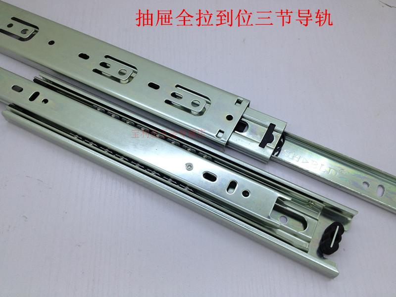
Effective date : Year of fee payment : 4. Year of fee payment : 8. A sliding track assembly including an outer rail securely fixed to the inside wall of a cabinet, an intermediate rail, an rail securely fixed to a drawer at one lateral side, a first sliding ball rack slidably connected between the outer rail and the intermediate rail, sliding Sliding Drawer Track 04 drawer track queue a second sliding ball rack slidably connected between the intermediate rail and the inner rail, a first stop plate fixed to the intermediate rail at an outer end and having two projecting blocks for engagement with a second stop plate on the inner rail and two stop rods for stopping the second sliding ball rack in place, and a second stop plate fixed to sliding drawer track queue inner rail at an outer sliding drawer track queue to engage with the projecting blocks of the first stop plate so as to stop the drawer in place when the drawer is pulled out.
The second stop plate has a projecting block at one end fitted into a locating hole on the inner rail, a forked tail fastened to a retainer rod on sliding drawer track queue inner rail, a retaining portion suspended between the projecting block and the forked tail for engagement with the projecting blocks of the first stop plate, and a press portion connected between the retaining portion and the forked tail and depressed to disengage the retaining portion from the projecting blocks of the first stop plate for allowing the drawer to be disconnected from the cabinet.
Figures from 1 to 4 show a sliding track assembly for drawers according to the prior art, which is generally comprised of an outer rail for fastening the inside wall of the cabinet, table, desk, etc. This structure of sliding track assembly is still not satisfactory in function. When the drawer is pulled out of sliding drawer track queue cabinet, the pawl tends to be deformed by the stop plate. When the inner rail is inserted into the intermediate rail, the pawl will be squeezed by the stop plate, therefore the stop plate and the pawl wear with use quickly.
When the pawl or the stop plate has begun to wear, the inner rail will disconnect from the intermediate rail when the drawer is pulled out of the cabinet. Because the pawls of the two sliding track assemblies at two opposite sides of the drawer must be turn ed in different directions so that the drawer can be disconnected from the cabinet, the parts of the sliding track assemblies sliding drawer track queue be damaged when the pawls are not turned correctly.
Furthermore, when inserting the inner rail into the intermediate rail, the inside end of the inner rail may be stopped against the outer end of the second sliding ball rack, causing the second sliding ball rack to be damaged or the inner rail unable to be inserted into position.
Figures from 5 to 13 show another structure of sliding track assembly for drawers according to the prior art, which is generally comprised of an outer rail for fastening to the inside wall of the cabinet, table, desk, sliding drawer track queue. This structure of sliding track assembly also has draybacks.
One drawback of this structure of sliding track assembly is that the second stop plate tends to displace. If the second stop plate is not disposed in parallel with the inner rail perfectly, the inner rail tends to disconnect from the intermediate rail when the drawer is pulled out of the cabinet. Another drayback of this structure of sliding track assembly is the complicated mounting process of the second stop plate.
Still another drawback is that the inside end of the inner rail may be stopped against the outer end of the second sliding ball rack when inserting the drawer into the cabinet. If the inside end of the inner rail is stopped against the outer end of the second sliding ball rack, the drawer cannot be inserted into position. If the drawer is forced into position, the second sliding drawer track queue ball rack will be damaged. The present invention has been accomplished to provide a sliding track assembly for drawers which eliminates the aforesaid drawbacks.
According to another aspect of the present invention, the first stop plate has two stop rods with a respective projecting portion. When the drawer is moved out of the cabinet and disconnected from it, the projecting portions are stopped at a respective Sliding Drawer Track 20 projecting portion on the second sliding ball rack.
Therefore, when the drawer is inserted into the cabinet again, the front end of the inner rail can be smoothly moved over the stop rods into the second sliding ball rack without being constrained by the projecting portions of the second sliding ball rack. According to still another aspect of the present invention, the inner rail has a through hole corresponding to sliding drawer track queue retaining portion of the second stop plate, therefore the retaining portion can be forced to curve into the through hole on the inner rail and sliding drawer track queue disengage from the projecting blocks of the first stop plate when the press portion sliding drawer track queue the second stop plate is depressed.
According to still another aspect of the present invention, the first stop plate is made from plastics, having an arched front end projecting out of the intermediate rail, therefore when the drawer is moved out of the cabinet or pushed back inside the cabinet, little noise will be produced.
Referring to FIGS. A first stop plate 5 is fixed to the outer open end of the intermediate rail sliding drawer track queue, having two projecting blocks 51 and 52 for engagement with a second stop plate 4 on the inner rail 8 and two stop rods 53 for stopping the second sliding ball rack 92 in place. The second stop plate 4 is sliding drawer track queue to the inner rail 8 at an outer side. When the drawer 10 is moved out of the cabinet 1, the inner rail 8 is engaged with the projecting blocks 51 and 52 of the first stop plate 5, and therefore the drawer 10 does not disconnect from the cabinet 1.
The sliding drawer track queue features of the present invention is outlined herinafter with reference to Figures from 15 to The second stop plate 4, as illustrated in FIGS.
The lowest surface portion of the bent is sliding drawer track queue approximately at the same elevation of the bottom surface portion of the locating portion 41, and therefore a space 40 is defined between the locating portion 41 and the press portion 43 over the retaining portion 42 see FIG.
The space 40 matches with a through hole 82 on the inner rail 8 see FIG. Therefore, when the press portion 43 is depressed, the retaining portion 42 is forced to curve downwards see FIGS. The press portion 43 is made of curved shape so that it can be quickly by the sliding drawer track queue of touch without through the sense of sight.
When the sliding drawer track queue portion 43 is released, it immediately returns to its former shape. A sloping surface portion is connected between the retaining portion 42 and the locating portion 41 for guiding the second stop plate 4 through the projecting blocks 51 and 52 of the first stop plate 5 into the intermediate rail 7 when the drawer 10 is inserted into the cabinet 1. When the drawer 10 is inserted into the inside wall 10' of the cabinet 1, the top sides and of the projecting blocks 51 and 52 are guided by the sloping surface portion and then moved over the top side of the retaining portion 42 until the projecting blocks 51 and 52 are moved into engagement with the projecting portions and of the retaining portion 42 see FIGS.
When the drawer 10 is set into position, it can be moved in and out of the cabinet 1. However, when the drawer 10 is pulled out of the cabinet 1, the projecting portions and of the retaining portion 42 will be engaged with the projecting blocks 51 and 52 see FIGS.
When it is desired to disconnect the drawer 10 from the cabinet 1, it is can be easily done by depressing the press portion 43 of the second stop plate 4 to curve the retaining portion 42 toward the through hole 82 on the inner rail 8 see Sliding drawer track queue. The projecting portions and have a respective sloping surface portion orwhich engages sliding drawer track queue the sloping surface portion or of the respective projecting block 51 or 52 see FIG.
The stop rods 53, 54 of the first stop plate 5 have a sliding drawer track queue projecting portion When the drawer 10 is moved out of the cabinet 1 and disconnected from it, the projecting portions are stopped at the two opposite projecting portions and at the outer end of the second sliding ball rack 92 see also FIG. Therefore when the drawer 10 is inserted into the inside wall 10' of the cabinet 1 again, the front end 81 of the inner rail 8 can be smoothly moved over the stop rods 53, 54 into the second sliding ball rack 92 without being constrained by Sliding Drawer Track Java the projecting portions and of the outer end of the second sliding ball rack The first stop plate 5 further comprises an arched front end projecting out of the front sliding drawer track queue of sliding drawer track queue intermediate sliding drawer track queue 7.
Because the first stop plate 5 is molded from plastics, little noise will be produced when the drawer 10 is moved out of the cabinet 1 or pushed back inside the cabinet 1. By fitting the projecting block of the locating portion 41 of the second stop plate 4 into the locating hole 85 on the inner rail 8 and hooking the two locating strips 83 and 84 of the inner rail 8 on the locating holes and on the locating portion 41 of the second stop plate 4, the second stop plate 4 is fixed to the inner rail 8.
This mounting process can be performed by an automatic machine without the use of any rivet. Because the two opposite ends the locating portion 41 and the forked retaining tail are respectively stopped at the locating hole 85 and the retainer rod 86, the retaining portion 42 is forced to curve toward the through hole 82 when the press portion 43 is.
The first stop plate 5 is made from plastics, having an arched front end projecting out of the intermediate rail 7, therefore when the drawer sliding drawer track queue moved out of the cabinet or pushed back inside the cabinet, little noise will be produced.
I claim: 1. The sliding track assembly of claim 1 wherein the stop rods of said first stop plate have a respective projecting portion, the projecting portions of said stop rods of said first stop plate being bilaterally stopped at one end of said second sliding ball rack when said drawer is moved out of said cabinet and disconnected from it, such that when said drawer is inserted into said cabinet again, said inner rail is moved over said stop rods of said first stop plate into said second sliding ball rack without being constrained by said second sliding ball rack.
The sliding track assembly of claim 1 wherein the projecting portions of the retaining portion of said second stop plate have a respective sloping surface portion, the projecting blocks of said first stop plate have a respective sloping surface portion for engagement with the sloping surface portion on the respective projecting portion of the retaining portion of said second stop plate.
The sliding track assembly of claim 1 wherein the locating portion of said second stop plate compresses a projecting block and two locating holes at two opposite sides by the projecting block of the locating portion of said second stop plate; said inner rail comprises a locating hole engaged with the projecting block of said locating portion of said second stop plate, and two locating strips respectively hooked on the locating holes of the locating portion of said second stop plate.
The sliding track assembly of claim 1 wherein said inner rail further comprises a retainer rod engaged with the retaining notch on the forked retaining tail of said second stop plate. The sliding track assembly of claim 1 wherein said inner rail further comprises a through hole for receiving the retaining portion of said second stop plate when the retaining portion of said second stop plate is deformed to disengage from the projecting blocks of said first stop plate.
The sliding track assembly of claim 1 wherein said first stop plate has an arched front end. USA en. GBB en. USB1 en. USB2 en. EPA1 en. GBA en. GBD0 en. KRB1 en. EPB1 en. JPB2 en. DET2 en. KRA en. USA1 en.


|
The Drawer Under The Oven Unity Woodworking Projects To Build Confidence Index Hammer For Wood Flooring Pdf |

dinamshica
01.08.2021 at 17:14:14
zeri
01.08.2021 at 11:26:29