Sharpening Lathe Tools Metal,Rockler Products Near Me 60,Wod Workout At Home Twitter,General Finishes Gray Wood Stain Me - You Shoud Know
Our best Mini Lathe yet. Now with all steel gears, larger mm chuck and brushless motor. This hobby metalworking machine really is built to last, with many of the features and specs of far larger machines. The Warco WM 14 - now with a longer table for even more work space.
Top quality comes as standard on this compact variable speed metalworking mill. Some lathes have only one leadscrew that serves all carriage-moving purposes. For screw cutting, a half nut is engaged to be driven by the leadscrew's thread; and for general power feed, a key engages with a keyway cut into the leadscrew to drive a pinion along a rack that is mounted along the lathe bed.
The leadscrew will be manufactured to either imperial or metric standards and will require a conversion ratio to be introduced to create thread forms from a different family. To accurately convert from one thread form to the other requires a tooth gear, or on lathes not large enough to mount one, an approximation may be used.
Multiples of 3 and 7 giving a ratio of can be used to cut fairly loose threads. This conversion ratio is often built into the quick change gearboxes. This transposition gives a constant In its simplest form the carriage holds the tool bit and moves it longitudinally turning or perpendicularly facing under the control of the operator. The operator moves the carriage manually via the handwheel 5a or automatically by engaging the feed shaft with the carriage feed mechanism 5c.
This provides some relief for the operator as the movement of the carriage becomes power assisted. The handwheels 2a, 3b, 5a on the carriage and its related slides are usually calibrated, both for ease of use and to assist in making reproducible cuts.
The carriage typically comprises a top casting, known as the saddle 4 , and a side casting, known as the apron 5. The cross-slide 3 rides on the carriage and has a feedscrew which travels at right angles to the main spindle axis. This permits facing operations to be performed, and the depth of cut to be adjusted. This feedscrew can be engaged, through a gear train, to the feed shaft mentioned previously to provide automated 'power feed' movement to the cross-slide.
On most lathes, only one direction can be engaged at a time as an interlock mechanism will shut out the second gear train.
Cross-slide handwheels are usually marked in terms of the part's diameter , so one graduation representing. The compound rest or top slide 2 is usually where the tool post is mounted. It provides a smaller amount of movement less than the cross-slide along its axis via another feedscrew. The compound rest axis can be adjusted independently of the carriage or cross-slide.
It is used for turning tapers, to control depth of cut when screwcutting or precision facing, or to obtain finer feeds under manual control than the feed shaft permits.
Usually, the compound rest has a protractor marked in its base 2b , enabling the operator to adjust its axis to precise angles. The slide rest as the earliest forms of carriage were known can be traced to the fifteenth century.
In the tool-supporting slide rest with a set of gears was introduced by a Russian inventor Andrey Nartov and had limited usage in the Russian industry. The first fully documented, all-metal slide rest lathe was invented by Jacques de Vaucanson around It is likely that Maudslay was not aware of Vaucanson's work, since his first versions of the slide rest had many errors that were not present in the Vaucanson lathe.
In the eighteenth century the slide rest was also used on French ornamental turning lathes. The suite of gun boring mills at the Royal Arsenal , Woolwich , in the s by the Verbruggan family also had slide rests. The story has long circulated that Henry Maudslay invented it, but he did not and never claimed so.
The legend that Maudslay invented the slide rest originated with James Nasmyth , who wrote ambiguously about it in his Remarks on the Introduction of the Slide Principle , ; [2] later writers misunderstood, and propagated the error. However, Maudslay did help to disseminate the idea widely. It is highly probable that he saw it when he was working at the Arsenal as a boy. In , whilst he was working for Joseph Bramah , he made one, and when he had his own workshop used it extensively in the lathes he made and sold there.
Coupled with the network of engineers he trained, this ensured the slide rest became widely known and copied by other lathe makers, and so diffused throughout British engineering workshops.
A practical and versatile screw-cutting lathe incorporating the trio of leadscrew, change gears, and slide rest was Maudslay's most important achievement. The tool bit is mounted in the toolpost 1 which may be of the American lantern style, traditional four-sided square style, or a quick-change style such as the multifix arrangement pictured.
The advantage of a quick change set-up is to allow an unlimited number of tools to be used up to the number of holders available rather than being limited to one tool with the lantern style, or to four tools with the four-sided type.
Interchangeable tool holders allow all tools to be preset to a center height that does not change, even if the holder is removed from the machine. The tailstock is a tool drill , and center mount, opposite the headstock.
The spindle T5 does not rotate but does travel longitudinally under the action of a leadscrew and handwheel T1. The spindle includes a taper to hold drill bits, centers and other tooling.
The tailstock can be positioned along the bed and clamped T6 in position as dictated by the work piece. There is also provision to offset the tailstock T4 from the spindles axis, this is useful for turning small tapers, and when re-aligning the tailstock to the axis of the bed. The image shows a reduction gear box T2 between the handwheel and spindle, where large drills may necessitate the extra leverage.
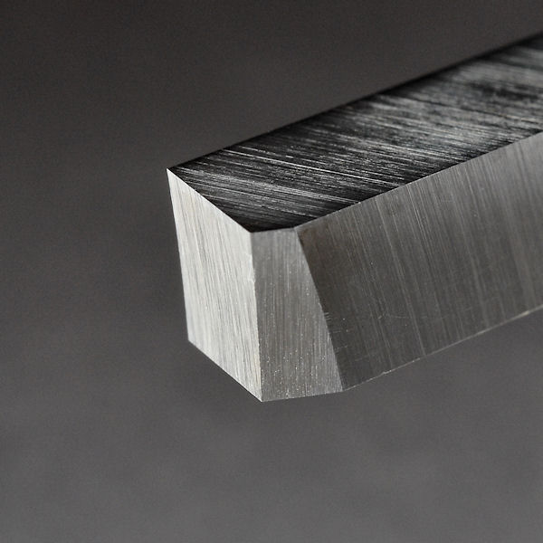
The tool bit is normally made of HSS, cobalt steel or carbide. Long workpieces often need to be supported in the middle, as cutting tools can push bend the work piece away from where the centers can support them, because cutting metal produces tremendous forces that tend to vibrate or even bend the workpiece. This extra support can be provided by a steady rest also called a steady , a fixed steady , a center rest , or sometimes, confusingly, a center.
A follower rest also called a follower or a travelling steady is similar, but it is mounted to the carriage rather than the bed, which means that as the tool bit moves, the follower rest "follows along" because they are both rigidly connected to the same moving carriage. Follower rests can provide support that directly counteracts the springing force of the tool bit, right at the region of the workpiece being cut at any moment.
In this respect they are analogous to a box tool. Any rest transfers some workpiece geometry errors from base bearing surface to processing surface. It depends on the rest design. For minimum transfer rate correcting rests are used. Rest rollers typically cause some additional geometry errors on the processing surface. There are many variants of lathes within the metalworking field. Some variations are not all that obvious, and others are more a niche area. For example, a centering lathe is a dual head machine where the work remains fixed and the heads move towards the workpiece and machine a center drill hole into each end.
The resulting workpiece may then be used "between centers" in another operation. The usage of the term metal lathe may also be considered somewhat outdated these days. Plastics and other composite materials are in wide use and, with appropriate modifications, the same principles and techniques may be applied to their machining as that used for metal.
The terms center lathe , engine lathe , and bench lathe all refer to a basic type of lathe that may be considered the archetypical class of metalworking lathe most often used by the general machinist or machining hobbyist. The name bench lathe implies a version of this class small enough to be mounted on a workbench but still full-featured, and larger than mini-lathes or micro-lathes. The construction of a center lathe is detailed above, but depending on the year of manufacture, size, price range or desired features, even these lathes can vary widely between models.
Engine lathe is the name applied to a traditional lateth-century or 20th-century lathe with automatic feed to the cutting tool, as opposed to early lathes which were used with hand-held tools, or lathes with manual feed only. The usage of "engine" here is in the mechanical-device sense, not the prime-mover sense, as in the steam engines which were the standard industrial power source for many years.
The works would have one large steam engine which would provide power to all the machines via a line shaft system of belts. Therefore, early engine lathes were generally 'cone heads', in that the spindle usually had attached to it a multi-step pulley called a cone pulley designed to accept a flat belt. Different spindle speeds could be obtained by moving the flat belt to different steps on the cone pulley.
Cone-head lathes usually had a countershaft layshaft on the back side of the cone which could be engaged to provide a lower set of speeds than was obtainable by direct belt drive. These gears were called back gears. Larger lathes sometimes had two-speed back gears which could be shifted to provide a still lower set of speeds. When electric motors started to become common in the early 20th century, many cone-head lathes were converted to electric power.
At the same time the state of the art in gear and bearing practice was advancing to the point that manufacturers began to make fully geared headstocks, using gearboxes analogous to automobile transmissions to obtain various spindle speeds and feed rates while transmitting the higher amounts of power needed to take full advantage of high speed steel tools.
Cutting tools evolved once again, with the introduction of man made carbides, and became widely introduced to general industry in the s. The headstock contains high-precision spinning bearings. Rotating within the bearings is a horizontal axle, with an axis parallel to the bed, called the spindle.
Spindles are often hollow and have an interior Morse taper on the spindle nose i. Spindles may also have arrangements for work-holding on the left-hand end of the spindle with other tooling arrangements for particular tasks. Spindles are powered and impart motion to the workpiece. The spindle is driven either by foot power from a treadle and flywheel or by a belt or gear drive from a power source such as electric motor or overhead line shafts.
In most modern lathes this power source is an integral electric motor, often either in the headstock, to the left of the headstock, or beneath the headstock, concealed in the stand. In addition to the spindle and its bearings, the headstock often contains parts to convert the motor speed into various spindle speeds.
Various types of speed-changing mechanism achieve this, from a cone pulley or step pulley, to a cone pulley with back gear which is essentially a low range, similar in net effect to the two-speed rear of a truck , to an entire gear train similar to that of a manual-shift automotive transmission. Some motors have electronic rheostat-type speed controls, which obviates cone pulleys or gears. The counterpoint to the headstock is the tailstock, sometimes referred to as the loose head, as it can be positioned at any convenient point on the bed by sliding it to the required area.
The tail-stock contains a barrel, which does not rotate, but can slide in and out parallel to the axis of the bed and directly in line with the headstock spindle. The barrel is hollow and usually contains a taper to facilitate the gripping of various types of tooling. Its most common uses are to hold a hardened steel center, which is used to support long thin shafts while turning, or to hold drill bits for drilling axial holes in the work piece.
Many other uses are possible. Metalworking lathes have a carriage comprising a saddle and apron topped with a cross-slide, which is a flat piece that sits crosswise on the bed and can be cranked at right angles to the bed. Sitting atop the cross slide is usually another slide called a compound rest, which provides 2 additional axes of motion, rotary and linear. Atop that sits a toolpost, which holds a cutting tool , which removes material from the workpiece.
There may or may not be a leadscrew , which moves the cross-slide along the bed. Woodturning and metal spinning lathes do not have cross-slides, but rather have banjos , which are flat pieces that sit crosswise on the bed. The position of a banjo can be adjusted by hand; no gearing is involved.
Ascending vertically from the banjo is a tool-post, at the top of which is a horizontal tool-rest. In woodturning, hand tools are braced against the tool rest and levered into the workpiece. In metal spinning, the further pin ascends vertically from the tool rest and serves as a fulcrum against which tools may be levered into the workpiece. Unless a workpiece has a taper machined onto it which perfectly matches the internal taper in the spindle, or has threads which perfectly match the external threads on the spindle two conditions which rarely exist , an accessory must be used to mount a workpiece to the spindle.
A workpiece may be bolted or screwed to a faceplate , a large, flat disk that mounts to the spindle. In the alternative, faceplate dogs may be used to secure the work to the faceplate. A workpiece may be mounted on a mandrel , or circular work clamped in a three- or four-jaw chuck. For irregular shaped workpieces it is usual to use a four jaw independent moving jaws chuck.
These holding devices mount directly to the lathe headstock spindle. In precision work, and in some classes of repetition work, cylindrical workpieces are usually held in a collet inserted into the spindle and secured either by a draw-bar, or by a collet closing cap on the spindle. Suitable collets may also be used to mount square or hexagonal workpieces. In precision toolmaking work such collets are usually of the draw-in variety, where, as the collet is tightened, the workpiece moves slightly back into the headstock, whereas for most repetition work the dead length variety is preferred, as this ensures that the position of the workpiece does not move as the collet is tightened.
A soft workpiece e. A soft dead center is used in the headstock spindle as the work rotates with the centre. Because the centre is soft it can be trued in place before use. Traditionally, a hard dead center is used together with suitable lubricant in the tailstock to support the workpiece. In modern practice the dead center is frequently replaced by a running center , as it turns freely with the workpiece—usually on ball bearings—reducing the frictional heat, especially important at high speeds.
When clear facing a long length of material it must be supported at both ends. This can be achieved by the use of a traveling or fixed steady. If a steady is not available, the end face being worked on may be supported by a dead stationary half center. A half center has a flat surface machined across a broad section of half of its diameter at the pointed end.
A small section of the tip of the dead center is retained to ensure concentricity. Lubrication must be applied at this point of contact and tail stock pressure reduced. A lathe carrier or lathe dog may also be employed when turning between two centers. In woodturning, one variation of a running center is a cup center , which is a cone of metal surrounded by an annular ring of metal that decreases the chances of the workpiece splitting.
A circular metal plate with even spaced holes around the periphery, mounted to the spindle, is called an "index plate". It can be used to rotate the spindle to a precise angle, then lock it in place, facilitating repeated auxiliary operations done to the workpiece. Other accessories, including items such as taper turning attachments, knurling tools, vertical slides, fixed and traveling steadies, etc. When a workpiece is fixed between the headstock and the tail-stock, it is said to be "between centers".
When a workpiece is supported at both ends, it is more stable, and more force may be applied to the workpiece, via tools, at a right angle to the axis of rotation, without fear that the workpiece may break loose. When a workpiece is fixed only to the spindle at the headstock end, the work is said to be "face work".
When a workpiece is supported in this manner, less force may be applied to the workpiece, via tools, at a right angle to the axis of rotation, lest the workpiece rip free. Thus, most work must be done axially, towards the headstock, or at right angles, but gently.
When a workpiece is mounted with a certain axis of rotation, worked, then remounted with a new axis of rotation, this is referred to as "eccentric turning" or "multi-axis turning".
The result is that various cross sections of the workpiece are rotationally symmetric, but the workpiece as a whole is not rotationally symmetric. This technique is used for camshafts, various types of chair legs. Lathes are usually 'sized' by the capacity of the work that they may hold.
Usually large work is held at both ends either using a chuck or other drive in the headstock and a centre in the tailstock. To maximise size, turning between centres allows the work to be as close to the headstock as possible and is used to determine the longest piece the lathe will turn - when the base of the tailstock is aligned with the end of the bed.
The distance between centres gives the maximum length of work the lathe will officially hold. It is possible to get slightly longer items in if the tailstock overhangs the end of the bed but this is an ill-advised practice. The other dimension of the workpiece is how far off-centre it can be.
This is known as the 'swing' "The distance from the head center of a lathe to the bed or ways, or to the rest. The swing determines the diametric size of the object which is capable of being turned in the lathe; anything larger would interfere with the bed.
This limit is called the swing of the bed. The swing of the rest is the size which will rotate above the rest, which lies upon the bed. This makes more sense with odd-shaped work but as the lathe is most often used with cylindrical work, it is useful to know the maximum diameter of work the lathe will hold.
This is simply the value of the swing or centre height above the bed multiplied by two. For some reason, in the U. To be clear on size, it is better, therefore, to describe the dimension as 'centre height above the bed'. As parts of the lathe reduce capacity, measurements such as 'swing over cross slide' or other named parts can be found. The smallest lathes are "jewelers lathes" or "watchmaker lathes", which, though often small enough to be held in one hand are normally fastened to a bench.
The workpieces machined on a jeweler's lathe are often metal, but other softer materials can also be machined. Jeweler's lathes can be used with hand-held "graver" tools or with a "compound rest" that attach to the lathe bed and allows the tool to be clamped in place and moved by a screw or lever feed.
Graver tools are generally supported by a T-rest, not fixed to a cross slide or compound rest. The work is usually held in a collet, but high-precision 3 and 6-jaw chucks are also commonly employed.
Common spindle bore sizes are 6 mm, 8 mm and 10 mm. Most lathes commonly referred to as watchmakers lathes are of this design.
Derbyshire, Inc. Two bed patterns are common: the WW Webster Whitcomb bed, a truncated triangular prism found only on 8 and 10 mm watchmakers' lathes ; and the continental D-style bar bed used on both 6 mm and 8 mm lathes by firms such as Lorch and Star. Other bed designs have been used, such a triangular prism on some Boley 6. Smaller metalworking lathes that are larger than jewelers' lathes and can sit on a bench or table, but offer such features as tool holders and a screw-cutting gear train are called hobby lathes, and larger versions, "bench lathes" - this term also commonly applied to a special type of high-precision lathe used by toolmakers for one-off jobs.
Lathes of these types do not have additional integral features for repetitive production, but rather are used for individual part production or modification as the primary role. Lathes of this size that are designed for mass manufacture, but not offering the versatile screw-cutting capabilities of the engine or bench lathe, are referred to as "second operation" lathes.
Lathes with a very large spindle bore and a chuck on both ends of the spindle are called "oil field lathes". Fully automatic mechanical lathes, employing cams and gear trains for controlled movement, are called screw machines.


|
2 By 4 Woodworking Projects Design Soft Close Cabinet Slides 90 Best Bench Players 2020 3d Wood Workshop Gifts Llc |

KRUTOY_BAKINECH
27.04.2021 at 23:49:52
Tehluke
27.04.2021 at 15:10:39
Qruzin
27.04.2021 at 21:20:51