Lateral File Cabinet Locking Mechanism,Fine Woodworking Miter Saw Station Jp,Cabinet Router Bit Set 10,Woodworking Projects For Nursery Education - Good Point
Its part number is LQ. Like other high-end, high-quality lateral cabinets, this cabinet features a stylish design that is created by a smooth blending of its ergonomic features with its aesthetic profile. Also, just like Lorell , it comes with hanging file rails that support side-to-side filing.
Moreover, to open the drawers to access the files, one needs to use recessed drawer pulls with each drawer having a single pull — but these pulls in HON Brigade LQ are made from reinforced aluminum. However, unlike Lorell , the HON Brigade LQ uses a reinforced, weighted based as opposed to counterweights to prevent tipping; and it also comes with label holders.
This commercial-grade lateral file cabinet is equipped with a 2-sided lock mechanism, drawer extension restraint, a core-removable drawer lock, and 4 adjustable stabilization guides, which make it a well-built model. Moreover, its durable construction makes it scratch-resistant as well as dent-resistant. This model is marketed as a ready-to-use product, and it is 30inches long, Obviously, its length-to-width ratio marks it as a lateral file cabinet, but its length limits it to a single storage compartment.
As expected, the drawer storage length is 30inches. Its load-free weight is about pounds. Moreover, like other high-quality cabinets, it comes with a limited lifetime warranty.
It also boasts of SCS indoor advantage gold-category certification. This is a fully-stabilized, multi-utility floor-standing single-drawer file cabinet that comes with a sliding door and 2 unequally-sized posting shelves. These 2 shelves are configured to allow for one to have an open configuration. The lower shelf is positioned aside the lateral cabinet hence giving this model a credenza configuration.
The upper shelf is positioned above the lateral cabinet and lower shelf. This low-profile model can be transformed into a seat if one fits a seat cushion atop the cabinet, and a specially-designed cushion for this purpose is sold separately. This model is made by the U. S-based company, Lorell ; and its part number is LLR It can be upgraded to a 3-drawer model if one fits a 2-drawer cabinet, such as Lorell , on top of it instead of a seat cushion.
Its drawer extension system features an adjustable glide and a ball-bearing slide suspension system. Also, the sliding door that covers the drawer comes with a locking mechanism that allows one to lock the drawer compartment. To open the drawers to access the files, one needs to use an arch pull fitted on the sliding door.
This model is specially designed to be fitted in offices, including home offices, where it can store letter-sized, A4-sized, and legal-sized printed documents and their matching document files. Like Lorell , this model has a stylish design that features a smooth blend of it ergonomics and aesthetics. Like other commercial-grade lateral file cabinets, Lorell LLR a core-removable drawer lock, and 4 adjustable stabilization guides.
As expected, this cabinet is sold in a ready-to-use state, and it is 36inches long, Its drawer length limits it to a single drawer-storage compartment, and one can also use the adjacent open posting shelf to store file folders vertically. The top posting shelf is for storing small office accessories. Furthermore, like other high-quality cabinets, it comes with a limited lifetime warranty.
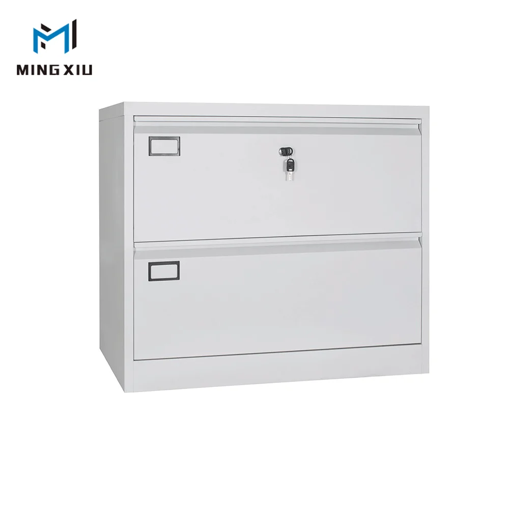
They are made of high-quality materials and are designed as heavy-duty models for handling rapid retrieval and insertion of file folders. This is a standalone, fully-stabilized heavy-duty two-drawer lateral file cabinet that features rugged construction, and whose drawer extension is supported by a full extension telescoping slide mechanism.
The file folders inside the drawers can be mobilized easily and quickly using either Kwik-Track or Mobile This model belongs to the Mobilizer series of file cabinets that is made by the U. S-based company, the Mayline Group.
Its telescoping suspension system that supports the drawer operation is lubricated by ball-bearings. It also comes with an optimized interlock system. This cabinet is made of high-grade, scratch-resistant galvanized steel with a medium-tone steel finish. It is is suited for office usage where it can store letter-sized, A4-sized, and legal-sized printed documents and their matching document files. This stylish, compact cabinet is shipped as ready-to-use office equipment that weighs about pounds.
It is 36inches long, Its overall design is a unique blend of its ergonomic and aesthetic features. As expected, the drawer length is 36inches. This heavy-duty model is equipped with hanging file rails that support side-to-side filing. There is also a recessed handle on each drawer for opening it. Additionally, the drawers are supported by an anti-tilt mechanism that prevents them from either damaging their slide rails or breaking the drawer panels if a fully loaded drawer is extended out completely.
Moreover, on the front panels of each drawer is attached to a label holder. This cabinet also comes with a drawer lock mechanism, core-removable drawer lock, and 4 adjustable stabilization guides, which gives it a sturdy and stable build.
Likewise, the use of high-quality steel makes the cabinet dent-resistant. With regards to its environmental certification, it boasts of GreenGuard Gold standard certification. This is a heavy-duty, space-saving, and fully stabilized four-drawer lateral file cabinet that can support both side-by-side and front-to-back filing.
It belongs to the series of file cabinets manufactured by the HON company. Even so, this specific model is made in Thailand. As a 4-drawer, it needs to be supported by vertical reinforcements to prevent it from toppling, and this is done by 4 vertical reinforcements.
Moreover, its smooth drawer operation is supported by a telescoping suspension system that features ball-bearings. It also has an optimized interlock system that allows for only one drawer to be opened at a time, while the other 3 drawers are held in a locked state by a stable lock mechanism that secures the two side panels of each drawer.
This cabinet is made of non-recyclable galvanized steel, and its final build features corrosion-inhibiting pre-treatment that is then followed by a putty finish. It, therefore, follows that its color scheme is putty. It is designed to resist scratches and dents. This large cabinet is suited for office use where it can store letter-sized, A4-sized, and legal-sized printed documents and their matching document files.
Its stylish design benefits from the seamless blending of its ergonomic features with its aesthetic profile. Moreover, to further stabilize its profile, it uses a reinforced case construction. Likewise, to access stored files, one needs to use a recessed drawer pulls with each drawer having a single pull. Beside each drawer, the handle is a label holder.
As a heavy-duty, commercial-grade file cabinet, it comes equipped with a secure drawer lock mechanism, drawer extension restraint, core-removable drawer lock, and 2 adjustable stabilization guides. The fully-assembled model has a load-free weight of about pounds; and is 30inches long, The drawer length of 30inches limits it to a single storage compartment. This is a heavy-duty, high-quality space-saving four-drawer lateral file cabinet whose commercial-grade construction allows for each drawer to be fitted with a magnetic label holder.
Its drawers feature full-width pull handles and dual locking bars. It is fully stabilized with its reinforced base and interlock system preventing undue toppling of the cabinet. It is designed for side-by-side filing; and it belongs to the Fortress Series inch line of file cabinets made by the US-based company, Lorell.
It is made from recyclable galvanized steel that is treated to a medium-tone finish. Like other high-quality and pricey file cabinets, it is designed to resist scratches and dents.
This 4-drawer model is supported by vertical reinforcements, while its drawer operation is supported by a telescoping suspension system that features ball-bearings. It also has an optimized interlock system that prevents the opening of 2 or more drawers. This cabinet is specially designed for office use where it is well-suited for storing letter-sized, A4-sized, and legal-sized printed documents and their matching document files.
Moreover, its stylish design benefits from the seamless blending of its ergonomic build with its aesthetic finish. Moreover, its reinforced case construction provides additional stability. This product has hanging file rails for side-to-side filing. Likewise, it comes equipped with a secure drawer lock mechanism, adjustable leveler, core-removable drawer lock, and ball-bearing suspension and slide system along with adjustable stabilization guides.
The fully-assembled, ready-to-use model is 42inches long, The drawer length of 42inches can allow one to compartmentalize the storage compartment into 2 sections, one inches long section for folder filing and the other for storing loose documents. These are lateral cabinet models whose retail price exceeds USD1, They are made of high-quality materials and feature high-end build designs.
The following 3 models are designed as heavy-duty cabinets for handling rapid retrieval and insertion of file folders. This is a heavy-duty, fully stabilized two-drawer lateral file cabinet with 3 posting shelves that are placed above the top drawer. It also has 2 hinged locking doors in the posting shelves compartment. It is designed for side-by-side filing.
This unique model is made in the U. In addition to such interlocks, past filing cabinets have also included locks that prevent any drawers from being opened when the lock is moved to a locking position. These locks are provided to address security issues, rather than safety issues. These locks override the interlocking system so that if the lock is activated, no drawers may be opened at all.
If the lock is not activated, the interlock system functions to prevent more than one drawer from being opened at the same time. Oftentimes the system that locks all of the drawers and the interlock system that locks all but one of the drawers are at least partially combined.
The combination of the locking system with the interlocking system can provide cost reductions by utilizing common parts. Past locking and interlocking mechanisms, however, have suffered from a number of disadvantages.
One disadvantage is the difficulty of changing the drawer configurations within a cabinet. Many filing cabinets are designed to allow different numbers of drawers to be housed within the cabinet. For example, in the cabinet depicted in FIG. For some cabinets, it would be possible to replace these three drawers with another number of drawers having the same total height as the three original drawers.
This reconfiguration of the drawers is accomplished by removing the drawer slides on each side of the drawer and either repositioning the drawer slides at the newly desired heights, or installing new drawer slides at the new heights. Many drawer slides include bayonet features that allow the drawer slides to be easily removed and repositioned within the cabinet.
For example, U. The height of these rods must be chosen to match the vertical spacing between each of the drawers in the system. If the cabinet is to be reconfigured, then new rods will have to be installed that match the height of the new drawers being installed in the cabinet.
Not only does this add additional cost to the process of reconfiguring the cabinet, it complicates the reconfiguring process by requiring new parts of precise dimensions to be ordered. Another difficulty with systems like that disclosed in the Sawatzky patent is the precise manufacturing that may be required to create these rigid rods.
These interlock systems only work if the rods have heights that fall within a certain tolerance range. This tolerance range, however, decreases as more interlocks are installed in a given cabinet.
In other words, the tolerance of the heights of these rods is additive. In order to function properly, a cabinet with ten drawers will therefore require smaller tolerances in the rods than a two drawer cabinet. In order to create rods that can be universally used on different cabinets, it is therefore necessary to manufacture the rods within the tight tolerances required by the cabinet having the greatest expected number of drawers.
These tight tolerances tend to increase the cost of the manufacturing process. Another difficulty with past interlock and lock systems for file cabinets has been the expense involved in creating a locking system that will withstand high forces exerted on the drawers.
Thus, if a file cabinet does not exceed this standard, thieves can gain access to the contents of a lock drawer by pulling the drawer outwardly with more than fifty pounds of force. Many users of file cabinets, however, desire their locking system to be able to withstand much greater forces than this before failure. Increasing the durability of the locking system often adds undesired expense to the cost of building the system.
A number of prior art interlock systems have used cables or straps as part of the interlocking system. Such systems, however, have suffered from other disadvantages.
The slack in the cable is decreased when a drawer is opened. The amount of slack of the cable is carefully chosen during the installation of the drawer lock so that there is just enough in the system to allow only one drawer to be opened at a time.
The interlock on whatever drawer is opened takes up this available slack in the cable, which prevents other drawers from being opened at the same time. A similar system is disclosed in U. This system uses a strap instead of a cable. Both systems suffer from the fact that excessive amounts of force may be easily transferred to either the cable or the strap. In other words, the cable or the strap itself are what resist the pulling force that a person might exert on a closed drawer when either the lock is activated, or another drawer is opened.
The tensile strength of the cable or strap therefore determines how much force must be exerted to overcome the interlock or lock. In fact, in the interlock of Westwinkel, the system appears to be constructed so that the pulling force exerted by a person on a locked drawer will be amplified before being applied to the strap. The strap must therefore have a greater tensile strength than the highest rated pulling force that the lock or interlock system can resist.
Increasing the strength of the cables or straps typically tends to increase their cost, which is desirably avoided. In light of the foregoing, the desirability of an interlock and lock system that overcomes these and other disadvantages can be seen. Accordingly, the present invention provides an interlock and lock that reduces the aforementioned difficulties, as well as other difficulties.
The interlock and lock of the present invention allow relatively low-tensile strength cables or flexible members to be used in systems which provide high resistance to theft and breakdown. The system of the present invention further allows changes to cabinet configurations to be easily implemented with little or no additional work required to integrate the new cabinet configuration into the interlock or lock system.
The present invention provides a simple construction for locks and interlocks that can be easily manufactured without excessively restrictive tolerances, and which can be easily installed in cabinets. According to one aspect of the present invention, an interlock for a cabinet drawer is provided.
The drawer is movable in the cabinet is a first direction toward an open position and in a second, opposite direction toward a closed position. The interlock includes an elongated, flexible member, a rotatable lever, an engagement member, and a biasing member. The lever is adapted to alter the amount of slack in the elongated, flexible member. The lever is rotatable between a first position and a second position.
The first position creates a low amount of slack in the elongated, flexible member, and the second position allows a high amount of slack to be present in the elongated, flexible member. The engagement member is attached to the drawer and positioned to cause the rotatable lever to rotate toward the first position when the drawer Filing Cabinet Locking Mechanism Us is initially moved from the closed position in the first direction. The biasing member is positioned adjacent the lever and adapted exert a biasing force that tends to prevent the lever from rotating from the first position to the second position until the drawer is moved in the second direction to the closed position.
According to another aspect of the present invention, an interlock is provided. The interlock includes a cable, a rotatable lever, an engagement member, and a retainer. The lever is adapted to change the cable between high and low slack conditions. The engagement member is attached to the drawer and positioned to cause the lever to rotate to a first position that changes the cable to a low slack condition when the drawer is initially moved in the first direction from the closed position.
The engagement member is also positioned such that a first force exerted on the drawer in the first direction is translated by the lever to a second force on the cable, which is less than the first force. The retainer is adapted to retain the rotatable lever in the first position while the drawer is moved to the open position.
According to still another aspect of the present invention, a locking and interlocking system for a cabinet is provided. The system includes a lock, a first cable, a second cable, a first interlock, and a second interlock. The first cable extends between at least a first and second drawer.
The first cable is changeable from a high slack to a low slack condition. The second cable extends between the lock and the first drawer. The lock is adapted to change the second cable from a high slack to a low slack condition.
The first interlock is in communication with the first and second cables and adapted to change both said first and said second cables from the high slack to the low slack condition whenever the first drawer is opened. The first interlock is further adapted to prevent the first drawer from opening whenever the first or second cables are in the low slack condition.
The second interlock is in communication with the first cable and adapted to change the first cable from the high slack to the low slack condition whenever the second drawer is opened. The second interlock is further adapted to prevent the second drawer from opening whenever the first cable is in the low slack condition.
According to yet another aspect of the present invention, a cabinet is provided that includes at least one drawer movable within the cabinet in a first direction toward an open position and in a second, opposite direction toward a closed position. The cabinet further includes a frame adapted to support the drawer, an elongated, flexible member, an interlock, and a slack take up mechanism. The elongated, flexible member is positioned within the cabinet and changeable between a lower slack condition and a higher slack condition.
The interlock is positioned within the frame and in operative engagement with the elongated, flexible member. The interlock is adapted to prevent the drawer from moving to the open position when the elongated, flexible member is in the lower slack condition and to allow the drawer to move to the open position when the elongated, flexible member is in the higher slack condition.
The slack take up mechanism is adapted to change the elongated, flexible member from the higher slack condition to the lower slack condition when the drawer is moved from the closed position to the open position. The slack take up mechanism is further adapted to translate a first force exerted on the drawer in the first direction to a second force exerted on the elongated, flexible member which is less than the first force. According to still other aspects of the present invention, the interlock may be in communication with a lock that is adapted to selectively alter the condition of the cable.
The interlocks may be secured to drawer slides that are removable from the cabinet. A cable guide may be included as part of the interlock to snap-fittingly receive the cable and retain it in engagement with the interlock.
The various aspect of the present invention provides an interlock and lock system that is versatile, resistant to high forces, and easily installed. These and other benefits of the present invention will be apparent to one skilled in the art in light of the following written description when read in conjunction with the accompanying drawings. The present invention will now be described with reference to the accompanying drawings wherein the reference numerals in the following written description correspond to like numbered elements in the several drawings.
The present invention relates to locks and interlocks that may be used with file cabinets, such as the file cabinet 60 depicted in FIGS.
File cabinet 60 includes three drawers 62 a—c that are essentially stacked on top of each other in file cabinet Each drawer can be pulled in a first direction 64 toward an open position. The lower most drawer 62 c in FIG. When it is time to close this drawer, it can be pushed in a second direction 66 back to its closed position.
The interlocking system of the present invention prevents more than one drawer from being opened at a single time. While only three drawers are illustrated in file cabinet 60 , the present invention is applicable to cabinets having any number of drawers.
The present invention also includes a locking system that overrides the interlocking system. That is, when the locking system is activated, no drawers can be opened at any time.
When the locking system is deactivated, the interlocking system is activated and prevents more than one drawer from being opened at a single time. The locking system may be activated by inserting a key into a keyhole 68 positioned at any suitable location on the file cabinet.
The locking and interlocking system are highly integrated so that many of the components of the interlocking system are also used in the locking system. The interlocks of the present invention may be advantageously combined or attached to the drawer slides in which drawers 62 slidingly move between their open and closed position. An example of one of these drawer slides 70 is depicted in FIG.
Each drawer 62 includes two drawer slides 70 , one positioned on one side of the drawer and another positioned on the opposite side of the drawer.
While the interlocks of the present invention can be placed at other locations besides on drawer slide 70 , the attachment of the interlocks to the drawer slide 70 allows the interlocks to be simultaneously removed and repositioned when the drawer slides 70 are removed and repositioned. This greatly facilitates the reconfiguration of a file cabinet 60 with differently sized drawers An interlock 72 according to a first embodiment of the present invention is depicted in FIG.
Interlock 72 is attached to a drawer slide Interlock 72 is operatively coupled to a cable 74 FIG. In general, interlock 72 operates according to the amount of slack in cable Specifically, cable 74 has two different basic levels of slack. When no drawers are opened and the lock is not activated, cable 74 has a high amount of slack in it. When a single drawer is opened, interlock 72 takes up most or all of the slack in cable 74 and creates a second, lower level of slack in cable The lower level of slack in cable 74 is such that no other drawers in the cabinet 60 can be opened.
This lower level of slack may be zero, or may include a small amount of slack. When the open drawer is closed, more slack in the cable 74 returns and any other single drawer may thereafter be opened. If a lock is included with the cabinet 60 , the lock is adapted to alter the slack in cable When in the locked position, the lock removes most or all of the slack in cable When in the unlocked condition, the lock allows cable 74 to have sufficient slack so that a single drawer may be opened.
Interlocks 72 are thus designed to only allow their associated or attached drawer to be opened when cable 74 has sufficient slack. Further, they are designed to remove substantially all of the slack in cable 74 , if their associated drawer is opened.
The detailed construction of interlock 72 , as well as how they accomplish the aforementioned functions, will now be described. Interlock 72 is adapted to be attached directly to a drawer slide While interlock 72 is depicted attached to the back ends of drawer slides 70 , it will be appreciated that it can be attached to the drawer slides at any desirable location along the drawer slides' length, or they can be attached directly to the cabinet.
Interlock 72 operates in conjunction with cable 74 so that only a single drawer can be open at a given time. If a lock is included in the cabinet, the lock is in communication with cable 74 and can change the amount of slack in cable If the lock is activated, cable 74 has little or no slack, and none of the drawers may be opened.
Interlock 72 allows a small portion of the pulling force exerted on a drawer in first direction 64 to be transmitted to cable Nevertheless, the amount of force transmitted is so small that a cable 74 having a relatively low tensile strength can still be used in a cabinet which provides strong resistance to its locking system being overcome.
As can be easily seen in FIG. Stationary portion 90 is fixedly secured to the interior of cabinet Stationary portion 90 includes an upper aperture and a lower aperture Upper aperture receives a first rivet that pivotally secures a lever to stationary portion Lower aperture receives a second rivet that pivotally secures a cam to stationary portion Interlock 72 further includes a cable guide 84 that is mounted to a pair of flanges 98 on stationary portion 90 Interlock 72 further includes a spring 82 and an engagement member Engagement member 86 comprises a flange that extends off of a slidable portion of drawer slide Slidable portion is slidable with respect to stationary portion 90 by way of a plurality of ball bearing cages that house a plurality of ball bearings in contact with both slidable portion and stationary portion 90 of drawer slide 70 FIGS.
Slidable portion is adapted to be secured to a drawer. Instead of the spring member 48 to urge the locking member 36 to the retracted position illustrated in FIG. Referring to FIG. Referring still to FIG.
The stop surface bears against the tab 34 when the locking bar 24 is moved downwardly to the position illustrated in FIG. A second locking member 70 is mounted on the rotatable shaft 38 in the same manner as locking member 36 so that when the projection 32 on the locking bar 24 moves upwardly, causing locking member 36 and shaft 38 to rotate in a clockwise direction referring to FIG.
Locking member 70 is also provided with a vertically extending tab portion 72 which engages a retaining element 74 which is attached to the left side of the file cabinet. The retaining element 72 has a downwardly depending lip File Cabinet Locking System Data 75 which is engaged by the upwardly extending tab on the left-hand locking member Since the retaining element 72 is directly attached to the file cabinet housing, the locking mechanism of this invention provides positive locking of both sides of the receding drawer front.
While the principles of the invention have now been made clear in the illustrative embodiment, it is entirely conceivable that upon examining the foregoing disclosure, those skilled in the art may devise embodiments of the concept involved which differ somewhat from the embodiments shown and described herein, or may make various changes in structural details to the present embodiment.
For example, the locking members 36 and 70 could be positioned on either side of the file cabinet, the locking bar 24 could be moved downwardly into locking position, and the shape of the various portions of the locking members could be changed. Consequently, all such changed embodiments or variations of structure as utilize the concepts of the invention and clearly incorporate the spirit thereof are to be considered as within the scope of the claims appended herebelow.
What is claimed is: 1. A locking mechanism for a file cabinet having a plurality of horizontally extensible drawers positioned one atop the other within a casing, each of said drawers having front and rear ends, a bottom wall, opposing first and second side walls, and a receding front wall being part of said casing, comprising: an elongated rod positioned adjacent said drawer first side wall, means for moving said rod vertically upwardly to a locked position and vertically downwardly to an unlocked position, a projection extending inwardly from said rod towards said drawer first side wall;.
The locking mechanism recited in claim 1, further comprising a tab member extending outwardly from said drawer first side wall towards said rod, said projection being positioned in the path of travel of said drawer tab member when said rod is in the locked position. The locking mechanism recited in claim 1, said first locking member engaging and locking means and said second locking member engaging and locking means each comprising a generally C-shaped portion.
The locking mechanism recited in claim 3, said first locking member cooperating means comprising a camming surface inclined downwardly from the end of the bottom leg of the C-shaped portion. The locking mechanism recited in claim 4, further comprising a stop surface being formed on said first locking member, said stop surface extending upwardly from the lowermost portion of said camming surface.
The locking mechanism recited in claim 5 said second locking member retainer engaging means comprising a tab extending horizontally from the rear surface of the C-shaped portion in a direction opposite to the legs of said C-shaped portion when said second locking member is in an unlocked position.
The locking mechanism recited in claim 1, further comprising means attached to said first locking member for urging said first locking member out of engagement with said drawer receding front wall.
The locking mechanism recited in claim 1, said urging means comprising a spring wound about said shaft, said spring first end being attached to said first locking member. A locking mechanism for a file cabinet having a plurality of horizontally extensible drawers positioned one atop the other within a casing, each of said drawers having front and rear ends, a bottom wall, opposing first and second side walls and a receding front wall comprising: an elongated rod positioned adjacent said drawer first side wall, means for moving said rod vertically upwardly to a locked position and vertically downwardly to an unlocked position, a projection extending inwardly from said rod towards said drawer first side wall;.
USA en. Device for controlling the opening and closing of a plurality of doors, each giving access to an enclosure.


|
Small Woodshop Layout 300 Tongue Groove Router Bit Set Item Garage Shop Dust Collection System Llc |

hmmmmmm
07.08.2020 at 15:36:33
PRINC_OF_LOVE
07.08.2020 at 12:39:37
BAKILI_QAQAS
07.08.2020 at 16:45:41